
Engine - dismantle and reassemble following operation 1004e10 - wash and check dismantled parts - refit cylinder head an
- Make
- Fiat
- Model
- Ulysse Factory Service Manual
- Year
- 2002–2010
- Section
- Engine and power unit › Engine - dismantle and reassemble following operation 1004e10 - wash and check dismantled parts - refit cylinder head an
ENGINE - DISMANTLE AND REASSEMBLE FOLLOWING OPERATION 1004E10 - WASH AND CHECK DISMANTLED PARTS - REFIT CYLINDER HEAD AND OIL SUMP - DOES NOT INCLUDE REPAIRS TO CYLINDER HEAD AND AUXILIARY UNIT
Dismantling
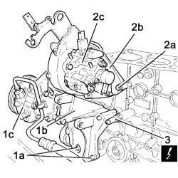
1. Undo the fixing bolts (1a) and remove the mounting (1b) complete with the power assisted steering pump (1c).
2. Undo the fixing bolts (2a) and remove the mounting (2b) complete with pressure pump (2c).
3. Undo and remove the minimum engine oil pressure sensor.
| Connector | Description |
|---|---|
| K030 | Sensor (switch) |
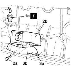
1. Undo and remove the minimum engine oil level sensor.
| Connector | Description |
|---|---|
| K032 | Engine oil level sensor |
2. Undo the fixing bolts (2a) and remove the turbocharger mounting bracket (2b).
3. Loosen the band (3a) and disconnect the turbocharger oil return pipe to the sump and remove it.
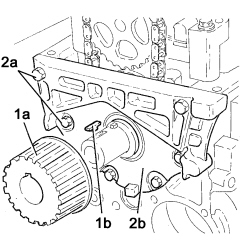
1. Undo the fixing bolt (1a) and remove the timing belt moving tensioner roller (1b).
2. Undo the fixing bolt (2a) and remove the timing belt fixed tensioner roller (2b).
3. Undo the fixing bolts (3a) and remove the water pump (1b) with gasket (3c).
1. Remove the timing belt toothed drive pulley (1a) and the key (1b).
2. Undo the fixing bolt (2a) and remove the crankshaft oil seal frontn cover (2b).
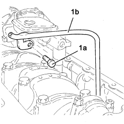
1. Undo the fixing bolts (1a) and remove the inner part of the guide (1b) for the engine oil dipstick.
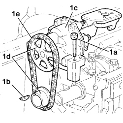
1. Undo the fixing bolts (1a) and key the key (1b) and remove the engine oil pump (1c) complete with gears (1d) and chain (1e).
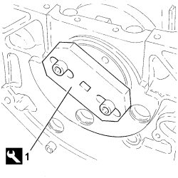
1. Position the tool for allowing the rotation of the crankshaft and secure it using the service bolts.
| Description | Code | Function |
|---|---|---|
| Flange | 1.860.815.000 | Crankshaft rotation |
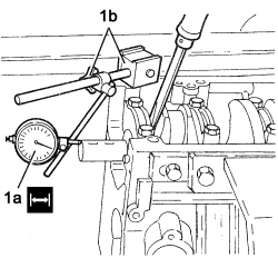
1. Fit a dial gauge (1a) with a magnetic base (1b) with the pointer in contact with the timing side of the crankshaft, as illustrated in the diagram.
- Using a suitable lever for leverage in both directions, measure the crankshaft endfloat and check that it is within the recommended values.
| Endfloat mm | Validity |
|---|---|
| - ÷ - |
If the value for the crankshaft endfloat does not correspond with the recommended figures, when refitting, regrind the crankcase seat and use suitable thrust washers (fastened to the central main bearing half) oversized by 0.XXXmm.
| Shim oversize mm | Validity |
|---|---|
| - ÷ - |
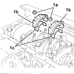
1. Undo and remove the connecting rod caps (1a) and the half-bearings (1c), following the procedure described below:
- Rotate the crankshaft using the tool fitted previously until cylinders nos.1 and 4 are at T.D.C.
- Undo the nuts (1a) and remove the connecting rod cap (1b) and the lower half-bearings for cylinders 1 and 4.
1. Remove the connecting rod-piston assemblies (1a) and the upper half bearings (1b) (crankcase side) for cylinders 1 and 4.
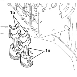
- Proceed in the same way for the removal of the pistons and the connecting rods for cylinders 2 and 3.
The number for the cylinder is stamped on the big ends and on the connecting rods to ensure correct refitting.
Mark the timing side for each piston to ensure they are in the correct position when refitting.
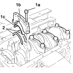
1. Undo the bolts (1a) and remove the main journal caps 2, 3, 4 and 5 (1b) and half-bearings (1c).
2. Remove the lower thrust washers for the 2nd main journal cap.
The main bearing caps are marked by an increasing number from the flywheel side for correct refitting.
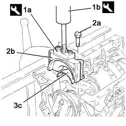
1. Fit the tool (1a) and the extractor (1b) on the 1st main bearing cap.
2. Undo the bolts (2a) and remove the 1st bearing cap (2b).
3. Remove the half-bearing
| Description | Code | Function |
|---|---|---|
| Extractor | 1.860.854.000 | Removal of 1st main bearing cap |
| Description | Code | Function |
|---|---|---|
| Grip | 1.846.011.000 | Removal of 1st main bearing cap |
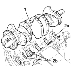
1. Remove the crankshaft.
2. Remove the half-bearings (2a) and upper thrust washers for the 2nd main bearing cap (2b).
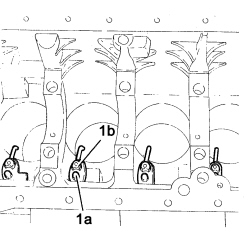
1. Undo the fixing bolts (1a) and remove the engine oil jets (1b).
- Clean the jets thoroughly and refit them tightening the fixing bolts to the recommended torque.
| Value daNm | Fastening | Component | dia | |
|---|---|---|---|---|
| 1a | (-) 1.0 | Bolts | ENGINE - Dismantling and Reassembly following Op. 1004E10 - Washing and checking dismantled components |
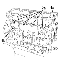
1. Undo the oil passage duct sealing plugs (1a) and (1b).
- Clean thoroughly, replace the seals and refit the plugs tightening to the recommended torque.
| Value daNm | Fastening | Component | dia | |
|---|---|---|---|---|
| 1a | (-) 4.0 | Plug | ENGINE - Dismantling and Reassembly following Op. 1004E10 - Washing and checking dismantled components |
| Value daNm | Fastening | Component | dia | |
|---|---|---|---|---|
| 1b | (-) 2.5 | Plug | ENGINE - Dismantling and Reassembly following Op. 1004E10 - Washing and checking dismantled components |
2. Drill and remove the sealing plugs (2a) and (2b) for the coolant circulation chambers, taking care not to damage the seats.
- Clean thoroughly, apply suitable sealant and refit the plugs using a suitable size drift.
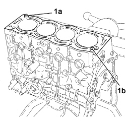
1. Extract the centering pins (1a) and (1b) then clean the cylinder head support plane thoroughly
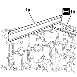
1. Using a calibrated metal rule (1a) and a feeler gauge (1b), check the planarity of the cylinder head - cylinder block/crankcase support surface.
2. If the measurement does not correspond to the recommended values, regrind the cylinder head support surface.
| Cylinder head support surface flatness | Validity |
|---|---|
| < 0.1, mm |
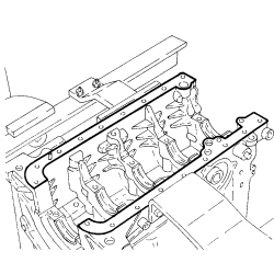
Clean any sealant resides from the oil sump support plane
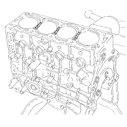
Clean the coolant channels between the cylinders thoroughly using a steel scourer.
- Carry out
Op. 1028H54 PISTON WITH CONNECTING ROD - DISMANTLING AT THE BENCH
- Carry out
- Carry out
Op. 1084B18 ENGINE OIL PUMP, REMOVED - CHECK AT BENCH
Reassembly
- Wash and check the appearance of all components removed.
- Lubricate all the mechanical components with engine oil.
- Measure the diameter of the cylinder bores and check that they correspond to the recommended figures.
| Cylinder liner ovality mm | Validity | |
|---|---|---|
| - ÷ - | ||
- Check that the ovality of the cylinder liners is within the recommended limits.
| Cylinder liner taper mm | Validity | |
|---|---|---|
| ± - | ||
- If the cylinder bore, taper or ovality measurements are not within the recommended limits, ream the cylinder bores following the recommended oversizes.
In the case of reaming, all the bores must have the same oversize.
| Cylinder liner bore diameter oversize mm | Validity | |
|---|---|---|
- Clean all the oil passage ducts inside the crankshaft using a compressed air jet and a pipe cleaner.
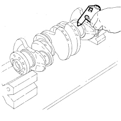
Check the static balance of the crankshaft resting the main journals on suitable parallels.
1. Measure the diameter of the main journals and check that they correspond to the recommended figures.
- Check that the diameter of the main journals corresponds to the recommended figures.
| Main journal diameter mm | Validity | |
|---|---|---|
| - ÷ - | ||
- If the diameter of the main journals is not correct, they should be reground to the recommended undersize.
Because the crankshaft has undergone nitriding, this treatment should be repeated and the size re-checked if it is ground.
| Main journal undersize mm | Validity | |
|---|---|---|
| - ÷ - | ||
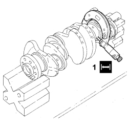
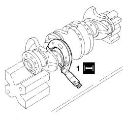
1. Measure the diameter of the crankpins and check that they correspond to the recommended figures.
| Main journal diameter mm | Validity | |
|---|---|---|
| - ÷ - | ||
- If the diameter of the crankpins is not correct, they should be reground to the recommended undersize.
The crankpins should always be ground to the same undersize grade so as not to alter the balance of the crankshaft.
Because the crankshaft has undergone nitriding, this treatment should be repeated and the size re-checked if it is ground.
| Crankpin undersize mm | Validity | |
|---|---|---|
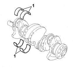
- Check the main bearings, noting that the half-bearings should not be adapted.
Replace them if scoring or signs of binding are noted.
The main journal and crankpin half-bearings are only available with an internal diameter undersize.
In the case of overhauling, the half-bearings to be used are marked with a white paint reference.
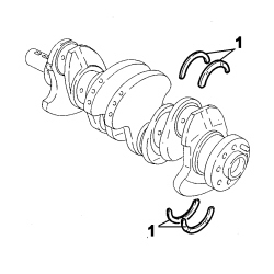
The upper and lower thrust washers are only available with an oversize washer.
The choice of thrust washers is made in order to produce the recommended endfloat.
The upper main journal half-bearings (crankcase side) have splining for oil distribution.
- Fit the upper main journal half-bearings in the crankcase seats ensuring that the openings for lubrication are aligned and everything is scrupulously clean. If the crankshaft has been reground, fit new and suitable oversize half-bearings in order to restore the original tolerance conditions.
1. Place the crankshaft carefully in position on the crankcase in order not to damage the surfaces of the half-bearings.
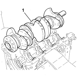
1. Apply a section of the calibrated wire (Plastigage) to measure the clearance of each main journal, parallel to the crankshaft axis, as illustrated.
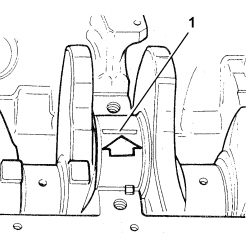
1. Fit the main bearing caps complete with half-bearings.
Fit the 1st cap (engine flywheel side) without gaskets and the 2nd cap without thrust washers.
1. Proceed with tightening the bearing caps following the procedure described below: - tighten to the recommended torque then, using the special tool, tighten to the recommended angular value.
Tighten the fixing bolts in a spiral pattern, starting from the inside.
| Value daNm | Fastening | Component | dia |
|---|---|---|---|
| (-) 2.5 ± 60° | Bolts | ENGINE, removed - Removing cylinder head(s) and oil sump for inspection |
| Description | Code | Function |
|---|---|---|
| Torque wrench | 1.860.942.000 | Tightening cylinder head bolts |
- Undo the fixing bolts and remove the main journal caps complete with lower half-bearings.
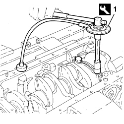
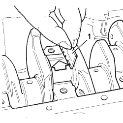
1. Proceed with measuring the radial clearance of each main journal using the special gauge (supplied together with the calibrated wire) for comparison with the width of the wire, as illustrated.
Check one main journal at a time, without rotating the crankshaft.
- Check that the clearance is within the recommended values.
| Clearance between crankshaft bearings - main journals mm | Validity |
|---|---|
| - ÷ - |
- After having check all the main journals, proceed with the definitive fitting of the crankshaft.
- Clean the main half-bearings thoroughly before fitting.
- If the half-bearings are being re-used, take care that they are correctly positioned in their original seats.
- Check that each half-bearing rests on the entire support surface. - Lubricate the parts involved with engine oil.
- Lubricate the parts involved with engine oil.
1. Position the crankshaft carefully in order not to damage the half-bearing surfaces.
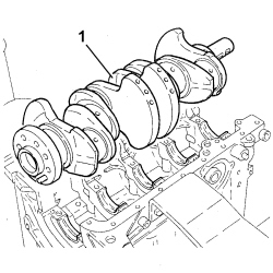
- Position the 3rd, 4th and 5th main bearing cap complete with half-bearings and screw in the fixing bolts without tightening to torque.
The lower main journal half-bearings (cap side) do not have splining for oil distribution.
- Position the 1st bearing cap complete with half-bearing following the procedure described below.
The 1st bearing cap also acts as a rear cover for the crankcase and comes with special gaskets.
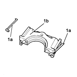
1. Fit both flexible side gaskets (1a) into the seats (1b) on the bearing cap.
The gaskets are supplied as spares already in the correct length: they should not therefore be shortened.
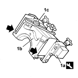
1. Position the tool (1a) on the bearing cap (1b) complete with gaskets and secure them using the bolts (1c).
| Description | Code | Function |
|---|---|---|
| Bracket | 1.860.808.000 | Fitting 1st main bearing cap |
Ensure the steel tabs for the tool fit over the step in the side of the cap, as illustrated.
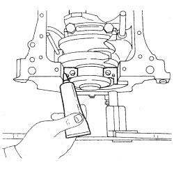
- Apply suitable sealant to the cap-crankcase mating surfaces and lubricate the sides of the crankcase housing.
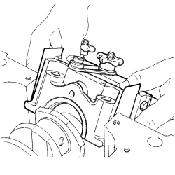
- Fit the cap, tilting it at first by around 45°, then straighten it and lower it carefully into the housing.
- Screw in the fixing bolts without tightening to torque, then release the tool horizontally.
The maximum permitted projection for the gaskets is 1 mm; otherwise the operation must be repeated.
- Position the 2nd bearing cap complete with half-bearing and thrust washers following the procedure described below.
1. Fit the upper thrust washers (1a) - (crankcase side)
Take care that the splined part of the thrust washers is facing the crankshaft.
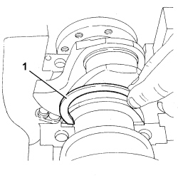
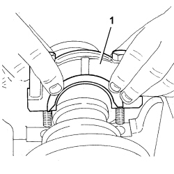
1. Position the 2nd bearing cap complete with thrust washers.
Take care that the splined part of the thrust washers is facing the crankshaft.
- Screw in the fixing bolts without tightening to torque.
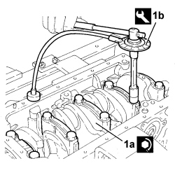
1. Proceed with tightening the bearing caps following the procedure described below:
- tighten to the recommended torque then, using the special tool, tighten to the recommended angular value.
Tighten the fixing bolts in a spiral pattern, starting from the inside.
| Value daNm | Fastening | Component | dia |
|---|---|---|---|
| 2.5 ± 60° | Bolts | ENGINE, removed - Removing cylinder head(s) and oil sump for inspection |
| Description | Code | Function |
|---|---|---|
| Torque wrench | 1.895.897.000 | Tightening cylinder head bolts |
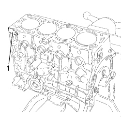
1. As illustrated below, check the reference, made by perforation, for the oversize during overhauling. This reference should correspond to the one on the piston crown.
- Carry out
- Carry out
Op. 1028H54 PISTON WITH CONNECTING ROD - DISMANTLING AT THE BENCH
The connecting rod-piston assemblies should be fitted with the flaring on the piston facing the engine oil filter side.
1. Fit the tool (1a) for compressing the piston rings on the piston and the subsequent fitting in the corresponding cylinder liner/bore, taking care to let the piston project at the bottom.
| Description | Code | Function | |
|---|---|---|---|
| 1a | Fitting tool | 1.860.700.000 | Introduction of connecting rod-piston assemblies in cylinder liners/bores |
- Lubricate the cylinder liner/bore.
- Rotate the crankshaft.
- Fit the piston/connecting rod assembly (1b), complete with half-bearing, positioning it with the bevel on the pinion facing the oil filter side.
- Fit the projecting part in the cylinder liner/bore.
- Keeping the tool adhering to the cylinder block/crankcase, tap the piston crown using a suitable size drift until it slips down into the cylinder liner/bore.
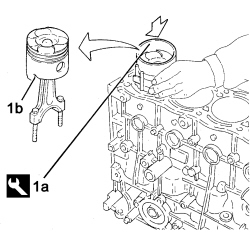
- Rotate the engine on the overhaul stand.
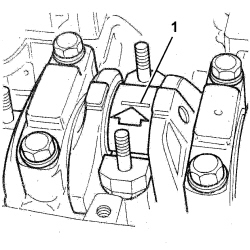
1. Fit the calibrated wire (Plastigage) on each crankpin, parallel to the crankshaft, as illustrated, to measure the clearance.
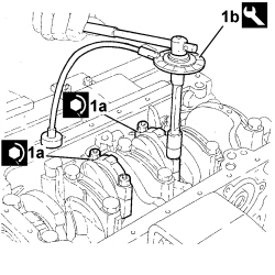
1. Fit the connecting rod caps (1a) complete with half-bearings and secure by tightening the nuts to the specified torque and then complete the tightening using the angular tightening tool (1b).
Fit the connecting rod caps so that the number stamped on each cap faces towards the same side as the number stamped on the big end.
| Value daNm | Fastening | Component | dia | |
|---|---|---|---|---|
| 1a | 2 + 70° | Nuts |
| Description | Code | Function | |
|---|---|---|---|
| 1b | 1.895.897.000 | Torque wrench | Angular tightening of bearing cap nuts |
- Then loosen the fixing nuts, remove the crankpin caps and the half-bearings.
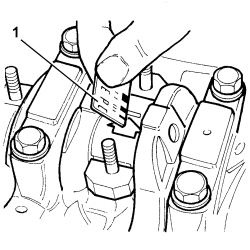
1. Proceed with measuring the radial clearance of the crankpins using the special gauge (supplied together with the calibrated wire) for comparison with the width of the wire, as illustrated.
Check one crankpin at a time, without rotating the crankshaft.
| Clearance between connecting rod bearings - crankpins mm | Validity |
|---|---|
| -÷ |
- If the value measured is not within the recommended figures, replace the connecting rod bearings.
- Fit the connecting rod caps complete with half-bearings and secure them tightening them to torque and then tightening them to the recommended angle using the special tool.
| Value daNm | Fastening | Component | dia |
|---|---|---|---|
| (-) 2 + 70° | Nuts | CONNECTING ROD and PISTON SET - R.R |
| Description | Code | Function |
|---|---|---|
| Torque wrench | 1.895.897.000 | Angular tightening of bearing cap nuts |
| Description | Code | Function |
|---|---|---|
| Flange | 1.860.815.000 | Crankshaft rotation |
- Remove the tool for rotating the crankshaft.
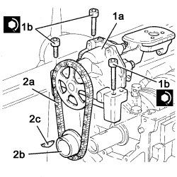
-1. Fit the engine oil pump (1a) and screw in the fixing bolts (1b) tightening them to the recommended torque.
| Value daNm | Component | Fastening | dia |
|---|---|---|---|
| ENGINE OIL PUMP - R.R. with crankcase sump removed | Bolts |
Ensure that the bolts (1a) and (1b) are correctly positioned in terms of length as illustrated in the diagram.
2. Fit the drive chain (2a), the drive gear (2b) and the key (2c).
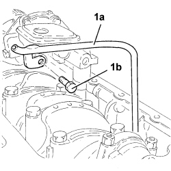
1. Position the inner part of the guide (1a) for the engine oil dipstick and tighten the fixing bolts (1b).
- Remove the crankshaft front cover oil seal, the oil seal is destroyed by this removal operation but take care not to damage the oil seal housing.
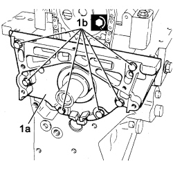
1. Apply a bead of plastic sealant to the contact surface of the crankshaft oil seal front cover (1a), position it correctly and tighten the fixing bolts (1b) by pre-tightening and then tightening to the recommended torque.
| Value daNm | Fastening | Component | dia |
|---|---|---|---|
| 0.7 | Bolt pre-tightening | ENGINE - Dismantling and Reassembly following Op. 1004E10 - Washing and checking dismantled components |
| Value daNm | Fastening | Component | dia |
|---|---|---|---|
| 1.5 | Bolts | ENGINE - Dismantling and Reassembly following Op. 1004E10 - Washing and checking dismantled components |
The fixing bolts are always replaced because they should not be reused.
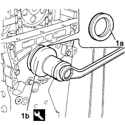
1. Fit a new crankshaft front cover oil seal (1a) using the special fitting tool (1b).
| Description | Code | Function | |
|---|---|---|---|
| 1b | Fitting tool | 1.860.855.000 | Fit the crankshaft front cover oil seal |
- Place the timing toothed drive pulley and the key in the housing on the crankshaft.
1. Fit a new flywheel side oil seal (1a) using the special fitting tool (1b).
| Description | Code | Function | |
|---|---|---|---|
| 1b | Fitting tool | 1.860.806.000 | Flywheel side oil seal fitting tool |
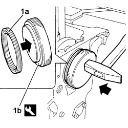
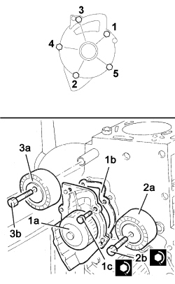
1. Place the water pump (1a) in its housing on the engine block complete with gasket (1b), screw in the fixing bolts (1c) and tighten in the order illustrated in the diagram below following the instructions:
- pre-tighten all the bolts (from 1 to 5) to the required torque;
| Value daNm | Fastening | Component | dia | |
|---|---|---|---|---|
| 1c | 0.5 | Bolt pretightening | WATER PUMP - R.R. with drive belt(s) removed |
- tighten all the bolts (from 1 to 5) to the required torque;
| Value daNm | Fastening | Component | dia | |
|---|---|---|---|---|
| 1c | 1.6 | Bolt pretightening | WATER PUMP - R.R. with drive belt(s) removed |
2. Position the fixed timing belt tensioner (2a) and tighten the retaining bolt (2b) to the recommended torque.
| Value daNm | Fastening | Component | dia | |
|---|---|---|---|---|
| 1c | 4.3 | Bolt | Timing belt FIXED TENSIONER - R.R. with timing belt removed |
3. Position the moving timing belt tensioner (3a) and screw in the the retaining bolt (3b) without tightening it.
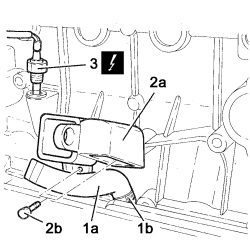
1.Position the turbocharger oil return pipe (1a) to the sump, connect it to the mounting on the engine block and tighten the retaining band (1b).
2. Position the turbocharger mounting bracket (2a) and tighten the fixing bolts (2b).
3. Position the minimum engine oil level sensor and tighten it to the recommended torque.
| Connector | Description |
|---|---|
| K032 Engine oil level sensor |
| Value daNm | Fastening | Component | dia |
|---|---|---|---|
| Sensor | ENGINE - Dismantling and Reassembly following Op. 1004E10 - Washing and checking dismantled components |
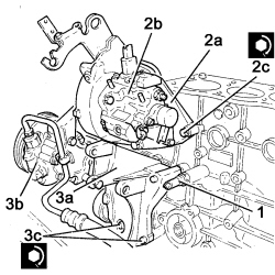
1. Position the minimum engine oil pressure sensor and tighten it to the recommended torque.
| Value daNm | Fastening | Component | dia |
|---|---|---|---|
| Sensor | ENGINE - Dismantling and Reassembly following Op. 1004E10 - Washing and checking dismantled components |
2. Position the support (2a) complete with pressure pump (2b) and screw in the fixing bolts (2c) and tighten to the recommended torque.
| Value daNm | Fastening | Component | dia | |
|---|---|---|---|---|
| 2c | Bolts | ENGINE - Dismantling and Reassembly following Op. 1004E10 - Washing and checking dismantled components |
3. Place the support (3a), complete with power assisted steering pump (3b), in its housing on the crankcase, screw in the fixing bolts (3c) then tighten in the order illustrated in the diagram following the instructions below:
- pre-tighten all the bolts (from 1 to 5) to the required torque;
| Value daNm | Fastening | Component | dia | |
|---|---|---|---|---|
| 3c | 1.0 | Bolt pre-tightening | ENGINE - Dismantling and Reassembly following Op. 1004E10 - Washing and checking dismantled components |
- tighten all the bolts (from 1 to 5) to the required torque;
| Value daNm | Fastening | Component | dia | |
|---|---|---|---|---|
| 3c | 2.2 | Botl tightening | WATER PUMP - R.R. with drive belt(s) removed |
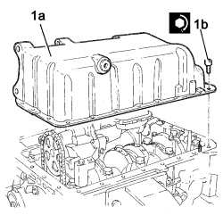
1. Apply a plastic seal to the engine oil sump (1a) fitting surface, then fit it and tighten the bolts (1b) to the recommended torque.
| Value daNm | Fastening | Component | dia | |
|---|---|---|---|---|
| 1b | Nuts | crank case oil sump - r + r and replace gasket with engine removed |
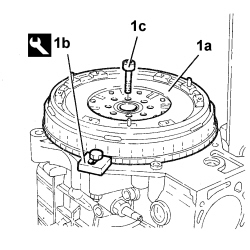
1. Fit the engine flywheel (1a) and use the flywheel lock (1b). Apply a thread-locking agent and tighten the bolts (1c) to the recommended torque.
| Description | Code | Function | |
|---|---|---|---|
| 1b | Counter-torque | 1.860.846.000 | Engine flywheel lock |
| Value daNm | Fastening | Component | dia | |
|---|---|---|---|---|
| 1c | 4.8 | Bolts | ENGINE FLYWHEEL - R.R. for versions with manual gearbox |
- Undo the fixing bolt and remove the flywheel lock.
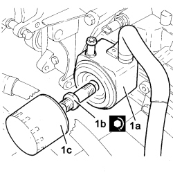
1. Position the engine oil heat exchanger (1a) complete with pipe and tighten the pin (1b) to the recommended torque.
| Value daNm | Fastening | Component | dia | |
|---|---|---|---|---|
| 1b | Pin | Engine oil HEAT EXCHANGER - R.R. |
2. Position and tighten the engine oil filter cartridge.
- Position the engine oil dipstick and fit the guide.
- Position the engine oil filler, complete with vapour recirculation pipe and tighten the band.
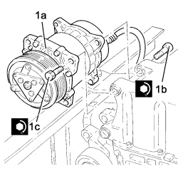
1. Position the air conditioning compressor (1a) in its housing, secure it using the bolts and tighten to the recommended torque starting with the pulley side bolts (1c) and finishing with the rear bolts (1b).
| Value daNm | Fastening | Component | dia | |
|---|---|---|---|---|
| 1b | 4.8 | Bolts | Air conditioning COMPRESSOR - R.R. - Includes fluid level check and top up if necessary |
| Value daNm | Fastening | Component | dia | |
|---|---|---|---|---|
| 1c | 4.8 | Bolts | Air conditioning COMPRESSOR - R.R. - Includes fluid level check and top up if necessary |
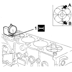
1. Measure the projection (1a) of the pistons from the cylinder head gasket support plane using a dial gauge and tool (1b) as described below:
- place the piston in question at T.D.C.;
- bring the pointer in contact with control point A, shown in the diagram, and zero the dial gauge;
- move the pointer on the engine block plane and read value S1;
- bring the pointer in contact with control point B, shown in the diagram, and zero the dial gauge;
- move the pointer on the engine block plane and read value S2.
The projection for the piston in question is the average value of the two readings
S = (S1 + S2) / 2
Repeat the above procedure for the remaining three pistons and check that the maximum difference between the projections is less than 0.07 mm.
| Description | Code | Function | |
|---|---|---|---|
| 1b | Dial gauge support | 1.870.404.000 | SINGLE CYLINDER HEAD - R.R. and Replace gasket |
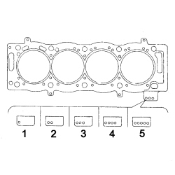
1. Select a new head gasket on the basis of the specified values.
The references indicate the oversizes.
Keep the gasket sealed in its nylon bag and do not remove from its protection until ready to fit.
Do not lubricate the gasket or contaminate with oil or grease.
| Piston projection | |||
|---|---|---|---|
| No. of refs 1 | No. of refs 2 | No. of refs 3 | No. of refs 4 |
| 0.55 ÷ 0.60 | 0.61 ÷ 0.65 | 0.66 ÷ 0.70 | 0.71 ÷ 0.75 |
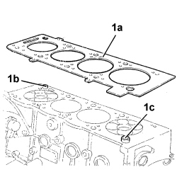
1. Position the reference pins (1a) and (1b), then position the correct size head gasket (1c) centering it on the actual reference pins.
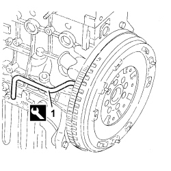
1. Fit the T.D.C. reference tool in the opening in the cylinder block and in the corresponding opening in the engine flywheel.
| Description | Code | Function | |
|---|---|---|---|
| 1 | Flywheel lock | 1.860.863.000 | Tool for timing crankshaft. |
1. Position the cylinder head centering it on the reference pins.
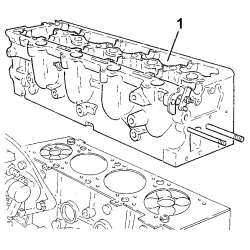
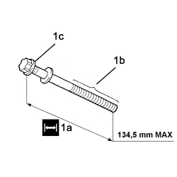
1. Check that the length of the bolts (1a) securing the cylinder head is within the recommended values (nominal length 131.5 mm - maximum value 134.5 mm). If this is not the case, replace the actual bolts. Lubricate the threads (1b) and the support planes (1c) of the bolts with engine oil.
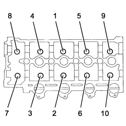
Tighten the cylinder head fixing bolts following the order illustrated and the instructions below:
- carry out a pre-tightening cycle (from 1 to 10) then a tightening cycle (from 1 to 10) to the recommended torque;
| Value daNm | Fastening | Component | dia |
|---|---|---|---|
| 2.0 | Bolt pre-tightening | ENGINE, removed - Removing cylinder head(s) and oil sump for inspection |
| Value daNm | Fastening | Component | dia |
|---|---|---|---|
| 6.0 | Botl tightening | ENGINE, removed - Removing cylinder head(s) and oil sump for inspection |
- carry out a loosening of 360° (from 10 to 1);
- carry out a pre-tightening cycle (from 1 to 10) then a tightening cycle (from 1 to 10) to the recommended torque;
| Value daNm | Fastening | Component | dia |
|---|---|---|---|
| 2.0 | Bolt pre-tightening | ENGINE, removed - Removing cylinder head(s) and oil sump for inspection |
| Value daNm | Fastening | Component | dia |
|---|---|---|---|
| 6.0 | Botl tightening | ENGINE, removed - Removing cylinder head(s) and oil sump for inspection |
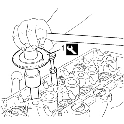
1. Lastly, carry out an angular tightening cycle (from 1 to 10) using the special torque wrench;
| Value daNm | Fastening | Component | dia |
|---|---|---|---|
| 220° ± 0.5° | Bolts | [ENGINE, removed - Removing cylinder head(s) and oil sump for inspection |
| Description | Code | Function | |
|---|---|---|---|
| Torque wrench | 1.860.942.000 | Tightening cylinder head bolts |
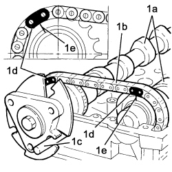
1. Position camshafts (1a) complete with chain (1b) as described below:
- use an 8 mm calibrated pin (1c) for timing the exhaust side camshaft;
- position the reference (1e) for timing the inlet side camshaft upwards.
- align the references (1d) and (1e), stamped on the camshafts with the black coloured links on the timing chain.
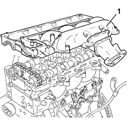
1. Apply sealant to the matching surface of the intake manifold/head cover with the cylinder head and place the intake manifold/head cover in position.
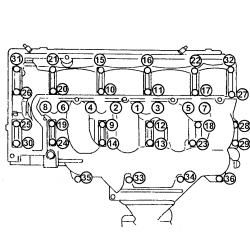
Tighten studs 1 to 8 to the recommended torque following the order illustrated in the diagram.
| Value daNm | Fastening | Component | dia |
|---|---|---|---|
| 1.0 | Studs | SINGLE CYLINDER HEAD - R.R. and Replace gasket |
Use a USAG 235 E6 spanner for tightening the studs
- carry out a pre-tightening cycle (from 9 to 36) then a tightening cycle (from 9 to 36) to the recommended torque on the intake manifold/head cover fixing bolts, following the order illustrated in the diagram;
| Value daNm | Fastening | Component | dia |
|---|---|---|---|
| 0.5 | Bolt pre-tightening | SINGLE CYLINDER HEAD - R.R. and Replace gasket |
| Value daNm | Fastening | Component | dia |
|---|---|---|---|
| 1.0 | Botl tightening | SINGLE CYLINDER HEAD - R.R. and Replace gasket |
- Remove the exhaust camshaft oil seal. This operation is destructive for the oil seal, but take care not to damage the oil seal seat.
1. Fit a new oil seal on the exhaust side camshaft (1a) using a special fitting tool (1b).
| Description | Code | Function | |
|---|---|---|---|
| 1b | Fitting tool | 1.870.821.000 | Fit the oil seal on the camshaft |
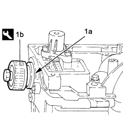
1. Fit flange (1a) into its seat on the exhaust end camshaft and tighten bolt (1b). Tighten to the specified torque using tool (1c) for counter-torque.
| Description | Code | Function | |
|---|---|---|---|
| 1c | Counter-torque | 1.860.776.000 | Lock the rotation of the camshaft |
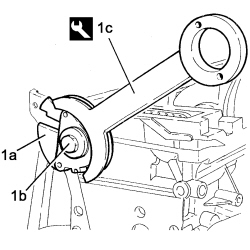
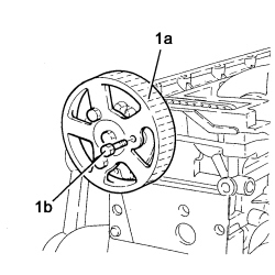
1. Fit the toothed driven pulley (1a) in its housing on the exhaust side camshaft flange and screw in the fixing bolts (1b) without tightening them.
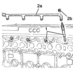
1. Fit the spark plugs (1a) and tighten them to the recommended torque.
| Value daNm | Fastening | Component | dia |
|---|---|---|---|
| Heater plugs | SINGLE CYLINDER HEAD - R.R. and Replace gasket |
2. Connect the electrical supply wiring (2a) to the plugs and secure it using the nuts (2b).
1. Lubricate and, if necessary, replace the gaskets (1a) and the oil filter (1b) for the vacuum unit.
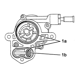
1. Position the vacuum unit (1a) and secure it using the nut (1b) and the bolts (1c) then tighten to the recommended torque.
| Value daNm | Fastening | Component | dia | |
|---|---|---|---|---|
| 1a | Nut | SINGLE CYLINDER HEAD - R.R. and Replace gasket |
| Value daNm | Fastening | Component | dia | |
|---|---|---|---|---|
| 1b | Bolts | SINGLE CYLINDER HEAD - R.R. and Replace gasket |
2. Position the connector (2a) for the oil vapour recirculation pipe and secure it using the bolt (2b).
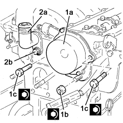
- Position the inlet side camshaft drive chain pre-tensioner and tighten the fixing bolts.
- Position the injectors and tighten the retaining nuts.
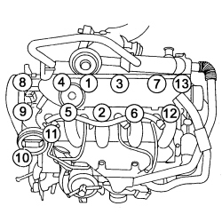
1. Position the tappet cover and tighten the fixing bolts.
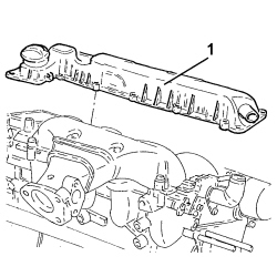
Tighten the tappet cover fixing bolts following the order illustrated and the instructions below:
- carry out a pre-tightening cycle (from 1 to 13) then a tightening cycle (from 1 to 13) to the recommended torque;
| Value daNm | Fastening | Component | dia |
|---|---|---|---|
| 0.5 | Bolt pre-tightening | ENGINE, removed - Removing cylinder head(s) and oil sump for inspection |
| Value daNm | Fastening | Component | dia |
|---|---|---|---|
| 1.0 | Botl tightening | ENGINE, removed - Removing cylinder head(s) and oil sump for inspection |
1. Position the rigid fuel supply pipe (1a) from the common rail to the injectors, screw in the connectors (1b) and tighten to the recommended torque.
| Value daNm | Fastening | Component | dia |
|---|---|---|---|
| Connectors | PIPES (all) from fuel MANIFOLD to INJECTORS - R.R. |
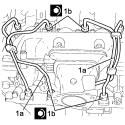
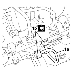
1. Position the rigid supply pipe (1a) from the pressure pump to the fuel manifold, screw in the connectors (1b) and tighten to the recommended torque.
| Value daNm | Fastening | Component | dia |
|---|---|---|---|
| Connectors | PIPE from PRESSURE PUMP to FUEL MANIFOLD - R.R. |
Each time work is carried out on the pipe from the pressure pump to the fuel manifold it must be replaced with a new one to prevent fuel leaks from the connectors.
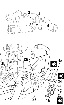
1. Position the inlet variable geometry solenoid valve (1b) and mounting bracket (1a).
2. Position the thermostat (2a) complete with pipes (2b), screw in the bolts (2c) and the nuts (2d) and tighten following the order illustrated and the instructions below:
- pre-tighten all the bolts (from 1 to 5) to the required torque;
| Value daNm | Fastening | Component | dia | |
|---|---|---|---|---|
| 2c | 1.0 | Bolt pre-tightening | THERMOSTAT UNIT - R.R. |
| Value daNm | Fastening | Component | dia | |
|---|---|---|---|---|
| 2d | 1.0 | Nut pre-tightening | THERMOSTAT UNIT - R.R. |
- tighten all the bolts (from 1 to 5) to the required torque;
| Value daNm | Fastening | Component | dia | |
|---|---|---|---|---|
| 2c | 2.5 | Botl tightening | THERMOSTAT UNIT - R.R. |
| Value daNm | Fastening | Component | dia | |
|---|---|---|---|---|
| 2d | 2.5 | Nut tightening | THERMOSTAT UNIT - R.R. |
- Position the connector for the water pump coolant inlet pipe and tighten the fixing bolts.
- Position the heat shield on the pipe.
- Connect the return pipe to the engine oil heat exchanger and, using the appropriate tool, tighten the band.
| Description | Code | Function |
|---|---|---|
| Caliper | 1.881.138.000 | Band opening |
- Connect the air conditioning compressor electrical connection.
| Connector | Description |
|---|---|
| L020 | Air conditioning compressor engagement electro-magnet |
- Position the engine block earth lead and tighten the fixing bolt.
| Connector | Description |
|---|---|
| C002 | Battery earth on engine |
- Connect electrical connection to the fuel pressure regulator and the electrical connection to the minimum engine oil pressure sensor.
| Connector | Description |
|---|---|
| N077 | Fuel pressure regulator |
| Connector | Description |
|---|---|
| K030 | Insufficient engine oil pressure sensor (switch) |
- Connect the glow plug electrical connections.
| Connector | Description |
|---|---|
| A040 | Heater plugs |
- Connect the electrical connection to the engine coolant temperature sensor.
| Connector | Description |
|---|---|
| K036 | Engine coolant temperature sensor/sender unit |
- Connect the electrical connection to the throttle control actuator solenoid.
| Connector | Description |
|---|---|
| L015 | Variable geometry intake solenoid valve |
- Tighten the bolt securing the cable loom duct.
- Secure the cable loom to the retaining bands.
- Position the throttle control actuator on the intake manifold ducts, complete with mounting bracket and tighten the fixing bolts and connect the rod.
- Tighten the fixing bolt for the oil dipstick guide pipe.
- Connect the oil vapour recirculation pipe and secure it to the band.
- Position the engine oil filler fitting and tighten the fixing bolt.
- Position the fuel heater complete with pipes.
- Connect the fuel heater connection.
| Connector | Description |
|---|---|
| O020 | Diesel pre-heating resistance |
- Connect the electrical connection to the fuel pressure sensor and the electrical connection to the fuel temperature sensor.
| Connector | Description |
|---|---|
| K083 | Fuel pressure sensor |
| Connector | Description |
|---|---|
| K081 | Fuel temperature sensor |
- Connect the return pipe rapid connectors to the fuel temperature sensor.
- Connect the fuel supply pipe to the pressure pump and tighten the band.
- Connect the excess fuel return pipe to the pressure pump and tighten the band.
- Connect the fuel return pipe to the injectors and secure the retaining clips.
- Position the fuel filter mounting bracket and tighten the fixing bolts.
- Position the fuel filter, complete with by-pass pipe, on the mounting bracket.
- Connect the fuel supply and return pipe rapid connectors to the fuel filter.
- Position the throttle body on the intake manifold and tighten the fixing bolts.
- Rotate the camshaft drive pulley in a clockwise direction until it is in the end of travel position in the slot.
- Tighten the fixing bolts manually and then loosen them by about 30°.
The camshaft drive pulley should be able to rotate freely.
- Rotate the moving timing tensioner in the minimum tension position and tighten the bolt to a torque of 0.1 daNm.
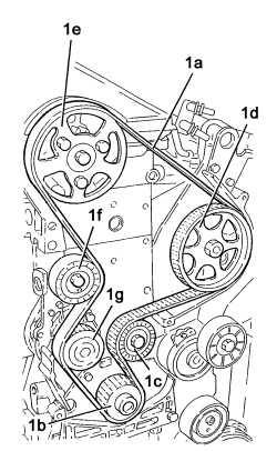
1-. Fit the toothed timing drive belt (1a) starting from the toothed drive pulley (1a) on the crankshaft; continuing on the fixed tensioner (1c), the pressure pump drive pulley (1d), the camshaft drive pulley (1e), the moving tensioner (1f) and finishing up with the water pump drive pulley (1g).
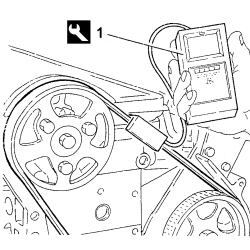
1. Fit the C.TRONIC - 105.5 tool for checking the timing drive belt tension on the section of the drive pulley between the camshaft and the pressure pump.
- Using a square 1/4" spanner (1a), adjust the moving tensioner (1b) in an anti-clockwise direction until the recommended tension is reached, then tighten the moving tensioner bolt (1c).
During this operation, check that the camshaft drive pulley is not in the end of travel position at the bottom of the slots, or else the procedure will have to be repeated.
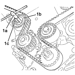
- Remove the C.TRONIC 105.5 tool.
1. Tighten the camshaft drive pulley fixing bolts (1a) to the recommended torque using the counter-torque tool (1b).
| Description | Code | Function | |
|---|---|---|---|
| 1c | Counter-torque | 1.860.831.000 | Lock the rotation of the camshaft |
| Value daNm | Fastening | Component | dia | |
|---|---|---|---|---|
| 1a | 2 | Bolts | TOOTHED timing BELT - R.R. for timing adjustment or replacement |
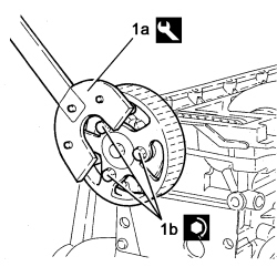
- Remove the flywheel lock fitted previously.
| Description | Code | Function |
|---|---|---|
| Flywheel lock | 1.860.846.000 | Tool for timing crankshaft |
- Remove the 8mm calibrated pin from the exhaust side camshaft.
- Remove the timing tool fitted previously.
| Description | Code | Function |
|---|---|---|
| Flywheel lock | 1.860.863.000 | Tool for timing crankshaft |
- Rotate the crankshaft through 8 revolutions without going backwards.
- Turn the engine clockwise without going back until the TDC reference tool fits into its seat on the flywheel.
| Description | Code | Function |
|---|---|---|
| Flywheel lock | 1.860.863.000 | Tool for timing crankshaft |
- Rotate the crankshaft until an 8 mm diameter calibrated pin can be inserted through the exhaust side camshaft drive pulley into the opening in the cylinder head.
- Loosen the bolts fixing the camshaft drive pulley using the counter-torque tool, then tighten them by hand making sure that the pulley rotates freely.
- Loosen the bolts fixing the tensioner, loosening the belt, then tighten the bolt by hand.
- Fit the C.TRONIC - 105.5 tool for checking the timing drive belt tension on the section of the drive pulley between the camshaft and the pressure pump.
| Timing belt tension | Validity |
|---|---|
| 48 - 55 |
- Using a square 1/4" spanner, adjust the tensioner in an anti-clockwise direction until the recommended tension is reached, then tighten the tensioner bolt to the recommended torque.
| Value daNm | Fastening | Component | dia |
|---|---|---|---|
| 2.3 | Moving tensioner bolts | TOOTHED timing BELT - R.R. for timing adjustment or replacement |
- Tighten the camshaft drive pulley fixing bolts using the counter-torque tool.
| Description | Code | Function |
|---|---|---|
| Counter-torque | 1.860.831.000 | Lock the rotation of the camshaft |
| Value daNm | Fastening | Component | dia |
|---|---|---|---|
| 2 | Bolts | TOOTHED timing BELT - R.R. for timing adjustment or replacement |
- Remove the C.TRONIC - 105.5 voltage mesuring equipment.
- Fit the C.TRONIC - 105.5 equipment again and check that the timing drive belt tension corresponds to the recommended figures.
| Timing belt tension | Validity |
|---|---|
| 48 - 55 |
- Remove the C.TRONIC -105.5 tool.
- Remove the timing tool fitted previously.
| Description | Code | Function |
|---|---|---|
| Counter-torque | 1.860.831.000 | Lock the rotation of the camshaft |
- Remove the 8mm calibrated pin from the exhaust side camshaft.
- Remove the flywheel lock fitted previously.
| Description | Code | Function |
|---|---|---|
| Flywheel lock | 1.860.863.000 | Tool for timing crankshaft |
- Turn the engine through two revolutions clockwise without going back until the TDC reference tool fits into its seat on the flywheel.
| Description | Code | Function |
|---|---|---|
| Flywheel lock | 1.860.863.000 | Tool for timing crankshaft |
- Visually inspect that the non alignment between the oepning in the camshaft pulley hub and the opening for the calibrated pin in the head is not more than 1 mm.
- Remove the timing tool fitted previously.
| Description | Code | Function |
|---|---|---|
| Flywheel lock | 1.860.863.000 | Tool for timing crankshaft |
1. Position the rigid power unit support, timing side (1a) and tighten the fixing bolts (1b) to the recommended torque.
| Value daNm | Fastening | Component | dia | |
|---|---|---|---|---|
| 1a | Bolts | ENGINE, removed - Removing cylinder head(s) and oil sump for inspection |
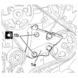
1. Position the protective timing covers (1a) and secure them using the bolts (1b).
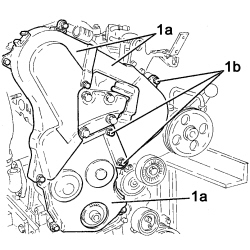
1. Fit the flywheel lock and tighten the fixing bolt.
| Description | Code | Function |
|---|---|---|
| Flywheel lock | 1.860.846.000 | Tool for timing crankshaft |
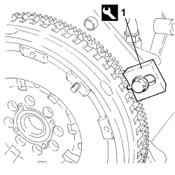
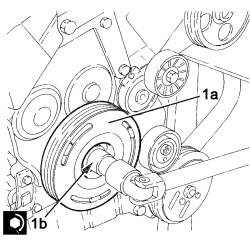
1. Position the auxiliary drive pulley (1a) and screw in the fixing bolt (1b) tightening it to the recommended angular value using the special torque wrench.
| Value daNm | Fastening | Component | dia |
|---|---|---|---|
| 5.0 ± 62° | Bolts | Crankshaft PULLEY - R.R. |
| Description | Code | Function |
|---|---|---|
| Torque wrench | 1.860.942.000 | Tightening cylinder head bolts |
Parts & tools for this job Staging For 2002 Fiat Ulysse
- PARTEngine gasket setSearch: Fiat Ulysse 2002 engine gasket set
- TOOLTorque wrenchSearch: 3/8 inch torque wrench
- TOOLFeeler gauge setSearch: feeler gauge set
Links open Amazon search results in a new tab. As an Amazon Associate I earn from qualifying purchases.