
Power unit with manual gearbox - r.r
- Make
- Fiat
- Model
- Ulysse Factory Service Manual
- Year
- 2002–2010
- Section
- Engine and power unit › Power unit with manual gearbox - r.r
POWER UNIT WITH MANUAL GEARBOX - R.R
Removing
Position the vehicle on a lift.
Op. 0010T84 COOLANT FOR AIR CONDITIONING SYSTEM - DEHYDRATE AND REPRESSURIZE
Op. 4450B12 FRONT WHEELS (TWO) - R+R
Op. 7055B90 LEFT FRONT WHEEL ARCH LINER - R.R.
Op. 7055B91 RIGHT FRONT WHEEL ARCH LINER - R.R.
Op. 7055B54 UNDER ENGINE PROTECTION/GUARD - R.R.
Op. 5540B78 LEFT FRONT LIGHT CLUSTER WITH DIRECTION INDICATOR AND FOG LIGHT - R.R.
Op. 5540B79 RIGHT FRONT LIGHT CLUSTER WITH DIRECTION INDICATOR AND FOG LIGHT - R.R.
Op. 5530B56 BATTERY DRIP TRAY COVER - R.R.
Disconnect the negative battery terminal.
Position a suitable container for collecting the coolant.
Disconnect the lower pipe from the radiator and completely drain the engine coolant.
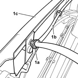
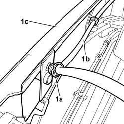
1. Open the retaining bands (1a) and release the headlamp washer fluid supply pipe (1b) from the front crossmember (1c).
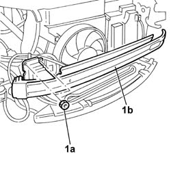
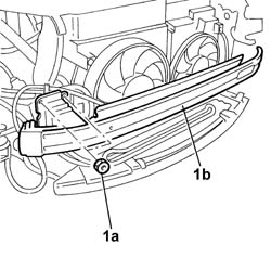
1. On both sides, undo the upper and lower fixing nuts (1a) and remove the upper front crossmember (1b).
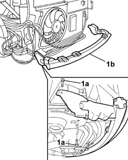
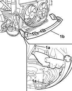
1. Undo the fixing bolts (1a), on both sides, and remove the lower crossmember (1b).
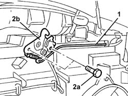
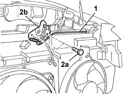
1. Disconnect the bonnet release control cable from the lock.
2. Undo the fixing nuts (2a) and remove the bonnet lock (2b) from the housing.
Disconnect the electrical connector for the bonnet opening switch, incorporated in the actual lock, for the alarm system.
1. Remove protective cover (1a) and detach relays (1b) from anchorage seat.
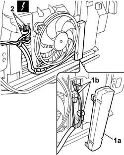
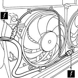
Release the electrical wiring for the engine fans from the retaining clips.
2. Disconnect the electrical connectors for the engine fans.
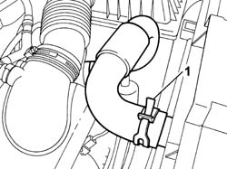
1. Open the retaining bands and disconnect the upper coolant pipe.
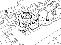
1. Undo retaining bolts (1a) and place engine oil filler fitting outside the working area (1b).
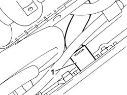
1. Disconnect the lower engine coolant pipe.
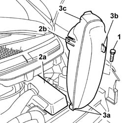
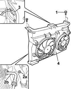
1. Undo the upper right and left retaining bolts for the radiator/fan assembly.
2. Disconnect the resonator from oil filter casing (2a) by undoing tabs (2b).
3. Raise the resonator by releasing from lower fittings (3a) and fitting (3b), then remove resonator (3c).
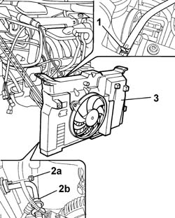
1. Disconnect the recirculation pipe from the radiator.
2. Undo retaining nuts (2a) and disconnect the pipe (2b) for the air conditioning unit from the condenser.
Disconnect the electrical connection for the linear sensor.
Release the power steering fluid pipes from the bands on the lower crossmember.
3. Remove the radiator-fan-condenser assembly.
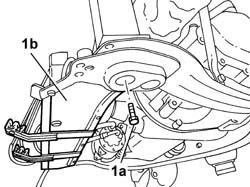
1. Undo the fixing bolts (1a) and remove the lower crossmember (1b).
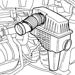
1. Disconnect the flexible input sleeve.
2. Remove the air filter casing from the housing.
1. Release the air filter casing flexible cold air intake pipe from the support.
2. Undo the fixing nuts and bolt.
3. Remove the mounting bracket complete with mechanical vehicle lifting device.
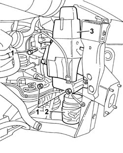
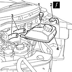
1. Undo the bolt fixing the engine coolant reservoir to the mounting bracket.
2. Disconnect the electrical connection for the engine coolant level sensor.
3. Disconnect the two engine coolant pipes from the rapid connectors.
4. Remove the engine coolant reservoir.
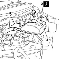
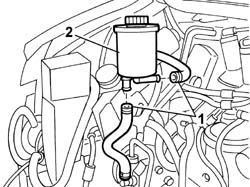
Open the power assisted steering fluid reservoir plug.
Remove the power assisted steering fluid filter from the housing in the reservoir.
Using a syringe, remove the power assisted steering fluid contained in the reservoir and collect it in a special container.
1. Disconnect the two power assisted steering system fluid pipes from the pump.
2. Release the power assisted steering pump fluid reservoir from the mounting and remove it.
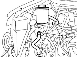
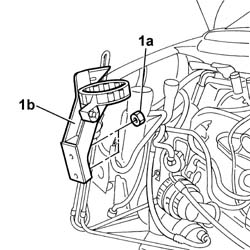
1. Undo retaining nuts (1a) and remove the two power assisted steering fluid reservoir mounting brackets.
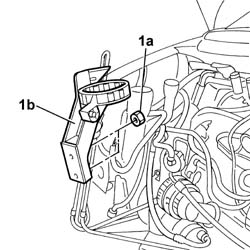
Op. 5010B18 HEATING VENTILATION UNIT AIR INTAKE - R+R
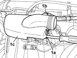
1. Work through hole (1a) indicated to loosen the bolt securing the retaining band, disconnect pipe (1b) and remove throttle body protective cover (1c).
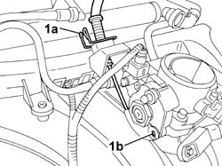
1. Remove retaining clip (1a) and disconnect accelerator control cable (1b) from the throttle body.
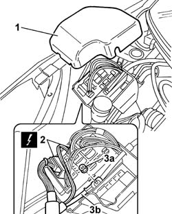
1. Lift up the engine compartment junction unit protective cover.
2. Disconnect the electrical connections from the engine compartment junction unit.
3. Undo the nut (3a) and separate the earth lead (3b) from the attachment on the control unit.
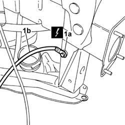
1. Undo bolt (1a) and remove gearbox earth lead (1b) from the body.
Op. 5010B18 HEATING VENTILATION UNIT AIR INTAKE - R+R
Disconnect the electrical connection for the power assisted steering fluid pressure sensor.
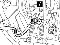
1. Disconnect the electrical connection for the reversing light switch.
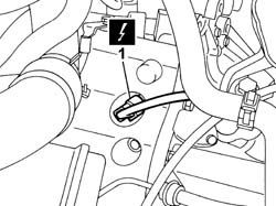
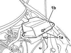
1. Undo the fixing bolts (1a) and remove the protective cover (1b) for the engine management control unit.
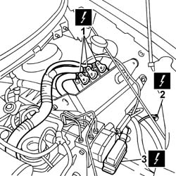
1. Disconnect the engine management unit electrical connections.
2. Undo the bolts and release the earth leads from the gearbox.
3. Disconnect the electrical connection for the ABS control unit.
Release the injection wiring from the retaining bands.
1. Undo retaining nuts (1a) and disconnect the two pipes (1b) for the air conditioning system from the air conditioning compressor.
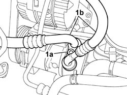
1. Undo the connector (1a) for the power assisted steering fluid pipe, undo the nut (1b) for the bracket and move the power assisted steering fluid pipe (1c) away from the work area.
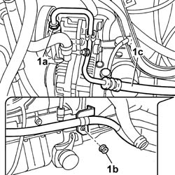
1. Disconnect fuel pipe (1a) and evaporation control system pipe (1b) from the quick-release fittings.
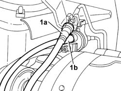
1. Disconnect the two heater supply and return pipes from the rapid connectors.
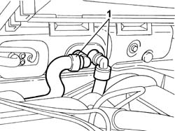
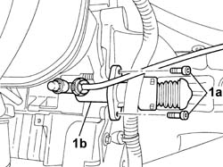
1. Undo the retaining bolts.
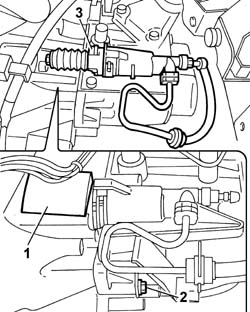
3. Remove the clutch control actuator cylinder without disconnecting the rigid pipe.
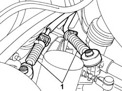
1. Prise up both heads, release the cables from the bracket and place outside the working area.
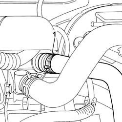
1. Disconnect the engine oil vapour pipe to the separator from the head.
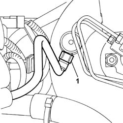
1. Disconnect the brake servo vacuum pipe from the quick-release fitting.
1. Undo the bolts securing the lower reaction rod.
2. Remove the lower reaction link.
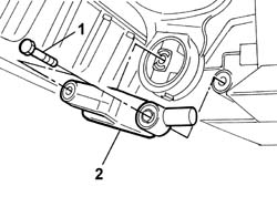
1. Undo the nut securing the collar joining the exhaust pipe to the manifold.
2. Separate the exhaust pipe section and remove the joining collar.
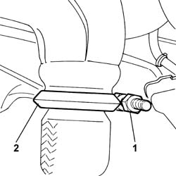
Have a suitable container for collecting the transmission fluid ready.
1. Undo the plug (1b), using a suitable spanner (1a), and drain the transmission fluid.
| Description | Code | Function | |
|---|---|---|---|
| 1a | Spanner | Wrench for slackening/tightening differential fluid plug |
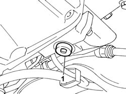
1. Undo the nut fixing the track rod end to the steering knuckle.
2. Extract the track rod end (2b) from the housing in the steering knuckle using the tool (2a).
| Description | Code | Function | |
|---|---|---|---|
| 2a | Head extractor | Ball joint removal |
Carry out the same operations on the remaining head.
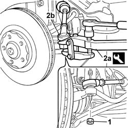
1. Undo the bolts fixing the steering knuckle to the shock absorber.
2. Release the inner driveshaft from the housing in the differential.
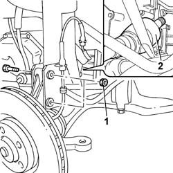
1. Working on the right side of the vehicle, remove the spring (1a), remove the split pin (1b) and undo the nut underneath.
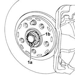
1. Undo the bolts fixing the steering knuckle to the shock absorber.
2. Fold the steering knuckle downwards and release the right driveshaft from the housing.
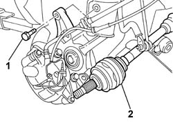
1. Undo the fixing nuts (1a) and remove the intermediate driveshaft and right driveshaft assembly (1b) from the wheel arch.
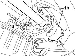
1. Undo the retaining bolts.
2. Remove the intermediate driveshaft support.
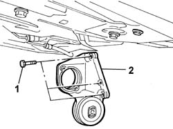
1. Disconnect both electrical connections for the Lambda sensors.
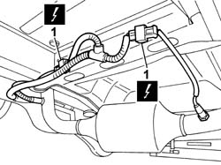
1. Disconnect the pipe from collar (1a), release electrical wiring (1b) secured to it, then remove lower engine coolant pipe (1c).
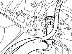
1. Undo and remove the engine oil filter element.
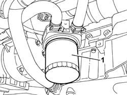
1. Use appropriate pliers to disconnect the coolant pipe from the heat exchanger.
| Description | Code | Function | |
|---|---|---|---|
| Caliper | Removing bands |
2. Undo pin (2a) and remove heat exchanger (2b).
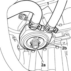
. Lower the vehicle.
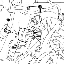
1. Undo retaining bolts (1a) and remove the upper power unit rod (1b).
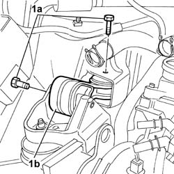
1. Fit mount (1a) and front bracket (1b). Secure to power unit crankcase.
| Description | Code | Function | |
|---|---|---|---|
| 1a | Tool for engine support | Removing power unit support |
| Description | Code | Function | |
|---|---|---|---|
| 1b | Engine mounting bracket | Removing power unit support |
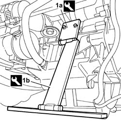
1. Fit the rear bracket and secure to the engine crankcase using the threaded holes in the intermediate drive shaft mount.
| Description | Code | Function | |
|---|---|---|---|
| 1 | Brackets | Removing power unit support |
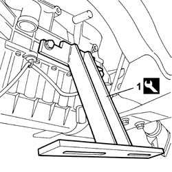
1. Postion the power unit support tool during removing and refitting (1a) on hydraulic lift (1b).
| Description | Code | Function | |
|---|---|---|---|
| 1a | Tool for removing and refitting power unit | Removing power unit support |
| Description | Code | Function | |
|---|---|---|---|
| 1b | Support | Removing power unit |
2. Secure brackets positioned prevoiusly on the support tool.
| Description | Code | Function | |
|---|---|---|---|
| 2 | Engine mounting bracket | Removing power unit support |
| Description | Code | Function | |
|---|---|---|---|
| Brackets | Removing power unit support |
3. Check that the support pins and blocks are positioned correctly and in contact with the power unit.
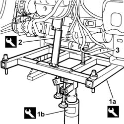
Completely lower the hydraulic support and the lift.
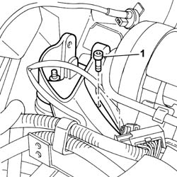
1. Undo the bolts securing the rigid support to the timing side of the power unit.
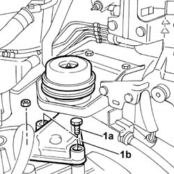
1. Undo the two bolts and the nut (1a) and separate the rigid power unit support (1b) from the gearbox and differential unit.
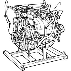
Manoeuvre the power unit turning it, then remove it from the engine compartment.
Take the greatest care not to damage parts fitted to the vehicle during engine rotation and removal.
Refitting
Support the power unit by means of a hydraulic lift fitted with the support tool and position the power unit in its compartment on the vehicle.
Take the greatest care not to damage parts fitted to the vehicle during engine installation.
Tighten the two bolts and the nut fixing the rigid power unit support to the gearbox-differential unit.
| Value daNm | Fastening | Component | dia | |
|---|---|---|---|---|
| 4.5 | Bolt | POWER UNIT GEAR BOX END RIGID MOUNT |
| Value daNm | Fastening | Component | dia | |
|---|---|---|---|---|
| 4.5 | Nut | POWER UNIT GEAR BOX END RIGID MOUNT |
Tighten the bolts fixing the timing side power unit rigid support to torque.
| Value daNm | Fastening | Component | dia | |
|---|---|---|---|---|
| 5.0 | Bolt | RIGID ENGINE MOUNT, TIMING SIDE |
Remove the fastenings for the brackets and the tool for supporting the power unit whilst removing and refitting.
| Description | Code | Function | |
|---|---|---|---|
| Support | Removing power unit |
Remove the hydraulic lift.
| Description | Code | Function | |
|---|---|---|---|
| Support | Removing power unit |
Remove the front bracket fastened to the power unit crankcase.
| Description | Code | Function | |
|---|---|---|---|
| Engine mounting bracket | Removing power unit support |
Remove the rear bracket fastened to the power unit crankcase.
| Description | Code | Function | |
|---|---|---|---|
| Brackets | Removing power unit support |
Fit the gearbox side rigid power unit support and tighten the fixing nuts and bolts.
Fit the timing side rigid power unit support and tighten the fastenings to torque.
Position the power unit upper rod and tighten the retaining bolts.
Remove the tool fitted previously for supporting and removing the unit from the power unit.
| Description | Code | Function | |
|---|---|---|---|
| Support | Removing power unit |
| Description | Code | Function | |
|---|---|---|---|
| Brackets | Removing power unit support |
1. Fit the upper power unit reaction link (1a) and tighten retaining bolts (1a) and (1c) to torque.
| Value daNm | Fastening | Component | dia | |
|---|---|---|---|---|
| 1b | 5.0 | Bolt | POWER UNIT REACTION ROD |
| Value daNm | Fastening | Component | dia | |
|---|---|---|---|---|
| 1c | 4.5 | Bolt | POWER UNIT REACTION ROD |
See descriptions
Op. 0010T21 ENGINE COOLANT - CHECK DENSITY AND CHANGE, IF NECESSARY
Raise the vehicle.
Fit the heat exchanger and tighten the fixing pin to torque.
| Value daNm | Fastening | Component | dia | |
|---|---|---|---|---|
| 5 | Pin | ENGINE OIL HEAT EXCHANGER |
Fit the pipes on the heat exchanger and restore the fastenings using special pliers.
| Description | Code | Function | |
|---|---|---|---|
| Caliper | Removing bands |
Fit the engine oil filter element and tighten it in the housing.
Fit the lower engine coolant pipe and restore the fastening to the rigid pipe using the band and fasten the electrical wiring secured to it.
Connect the electrical connections for the Lambda sensors.
Fit the intermediate driveshaft support and tighten the fixing bolts to torque.
| da Nm | Fastening | Component | dia |
|---|---|---|---|
| 4.5 | Bolt | INTERMEDIATE DRIVESHAFT SUPPORT |
Fit the intermediate driveshaft and right driveshaft assembly in the wheel housing and tighten the fixing nuts to torque.
| da Nm | Fastening | Component | dia |
|---|---|---|---|
| 1.75 | Nut | INTERMEDIATE DRIVE SHAFT |
Fit the right driveshaft in position and tighten the bolts fixing the steering knuckle to the shock absorber to torque.
| da Nm | Fastening | Component | dia |
|---|---|---|---|
| (Shock absorber) 9 | Bolts | FRONT HUB STRUT |
Working on the right side of the vehicle, tighten the fixing nut to torque, position the split pin and refit the fastening clip.
| da Nm | Fastening | Component | dia |
|---|---|---|---|
| (Driveshaft) 10+60° | Nut | FRONT HUBS WITH BEARINGS |
Fit the inner driveshaft in the housing in the differential.
Tighten the bolts securing the steering knuckle to the shock absorber to torque.
| Value daNm | Fastening | Component | dia | |
|---|---|---|---|---|
| (Shock absorber) 9 | Bolts | FRONT HUB STRUT |
Fit the steering track rod ends and tighten the nuts fixing them to the steering knuckles to torque.
| Value daNm | Fastening | Component | dia | |
|---|---|---|---|---|
| (steering knuckle) 4 | Nut | ADJUSTABLE STEERING LINK JOINTS (C-S) |
Tighten the transmission fluid plug using a suitable spanner.
| Description | Code | Function | |
|---|---|---|---|
| Spanner | Wrench for slackening/tightening differential fluid plug |
| Value daNm | Fastening | Component | dia | |
|---|---|---|---|---|
| 3.5 | Plug | GEAR CASING PADS |
Join the exhaust pipe and the exhaust manifold and tighten the nut fixing the exhaust pipe collar to the manifold to torque.
| da Nm | Fastening | Component | dia |
|---|---|---|---|
| 2.5 | Nut | PIPE JOIN COLLAR |
Fit the lower reaction rod and tighten the bolts fixing the lower reaction rod.
| da Nm | Fastening | Component | dia |
|---|---|---|---|
| 6.5 | Bolt | ROD TO SUPPORT FASTENING |
| da Nm | Fastening | Component | dia |
|---|---|---|---|
| 9.0 | Bolt | ROD TO FRAME FASTENING |
Connect the brake servo vacuum pipe rapid connector.
Connect the engine oil vapour pipe to the separator.
Fit the two heads and secure the flexible cables to the bracket.
Fit the clutch actuator cylinder and tighten the retaining bolts.
| da Nm | Fastening | Component | dia |
|---|---|---|---|
| 2.0 | Bolt | CLUTCH OPERATING/ACTUATOR CYLINDER |
Connect the two heater supply and return pipes to the rapid connectors.
Connect the rapid connectors for the fuel pipe and the evaporation control system pipe.
Position the power assisted steering fluid pipe, tighten the bracket nut and tighten the connector for the power assisted steering fluid pipe to torque.
| Value daNm | Fastening | Component | dia | |
|---|---|---|---|---|
| 2.5 | Nut | PIPE BTWN PUMP + POWER STEERING BOX |
Connect the two pipes for the climate control system and tighten the fixing bolt.
Secure the injection wiring using the retaining bands.
Connect the electrical connection for the ABS control unit.
Secure the gearbox earth leads and tighten the bolts.
Connect the electrical connections for the engine management control unit.
Fit the protective cover for the engine management control unit and tighten the fixing bolts.
Connect the electrical connection for the reversing light switch.
Connect the electrical connection for the power assisted steering fluid pressure sensor.
Secure the gearbox earth lead to the bodyshell and tighten the fixing bolt.
Fit the earth lead to the control unit retainer and tighten the fixing nut.
Connect the electrical connections to the engine compartment junction unit.
Fit the engine compartment junction unit protective cover.
Connect the accelerator control cable to the throttle casing and fit the fastening clip.
Fit the rigid pipe on the throttle casing and restore the fastening.
Fit the power assisted steering fluid reservoir mounting brackets and tighten the fixing nuts.
Secure the power assisted steering pump fluid reservoir to the mounting.
Connect the two power assisted steering system fluid pipes to the pump.
Fit the power assisted steering fluid filter in the reservoir.
Tighten the power assisted steering fluid reservoir plug.
Fit the engine coolant reservoir.
Connect the two engine coolant pipes rapid connectors.
Cconnect the electrical connection for the engine coolant level sensor.
Tighten the bolt fixing the engine coolant reservoir to the mounting bracket.
Fit the mounting bracket complete with mechanical vehicle lifting device and tighten the nuts and bolt.
Secure the air filter casing flexible cold air intake pipe to the support.
Fit the air filter casing in the housing.
Connect the flexible air inlet hose.
Fit the lower crossmember and tighten the fixing bolts to torque.
| Value daNm | Fastening | Component | dia | |
|---|---|---|---|---|
| 8 | Bolt | COOLANT RADIATOR SUPPORT BEAM |
Fit the radiator-fan-condenser assembly.
Secure the power steering fluid pipes to the bands on the lower crossmember.
Connect the electrical connection for the linear sensor.
Connect the air conditioning assembly pipe to the condenser and tighten the fixing nuts.
Connect the recirculation pipe for the radiator.
Position the resonator securing it to the retainers.
Connect the resonator to the air filter casing.
Tighten the upper retaining bolts for the radiator/fan assembly.
Connect the lower engine coolant pipe.
Fit the engine oil filler and tighten the fixing bolts.
Connect the upper engine coolant pipe and restore the fastening.
Connect the electrical connectors for the engine fans.
Secure the electrical wiring to the retaining clips.
Attach the relays to the housing and fit the protective cover.
Connect the electrical connector for the bonnet opening switch, incorporated in the actual lock, for the alarm system.
Place the bonnet lock in position and tighten the fixing nuts.
Connect the bonnet release control cable to the lock.
Carry out the bonnet lock adjustment: see op. 7025A10
Fit the lower crossmember and tighten the fixing bolts to torque.
Fit the upper front crossmember and tighten the fixing nuts to torque.
Secure the headlamp washer fluid supply pipe to the front crossmember.
Connect the lower radiator pipe.
Connect the negative battery terminal.
Op. 5530B56 BATTERY DRIP TRAY COVER - R.R.
Op. 5540B79 RIGHT FRONT LIGHT CLUSTER WITH DIRECTION INDICATOR AND FOG LIGHT - R.R.
Op. 5540B78 LEFT FRONT LIGHT CLUSTER WITH DIRECTION INDICATOR AND FOG LIGHT - R.R.
Op. 7055B54 UNDER ENGINE PROTECTION/GUARD - R.R.
Op. 7055B91 RIGHT FRONT WHEEL ARCH LINER - R.R.
Op. 7055B90 LEFT FRONT WHEEL ARCH LINER - R.R.
Op. 4450B12 FRONT WHEELS (TWO) - R+R
Op. 0010T84 COOLANT FOR AIR CONDITIONING SYSTEM - DEHYDRATE AND REPRESSURIZE
Op. 0010T21 ENGINE COOLANT - CHECK DENSITY AND CHANGE, IF NECESSARY
Op. 0010T40 CHANGE MANUAL GEARBOX OIL
Remove the vehicle from the lift.
- Operation not available.
Removing
Position the vehicle on a lift.
See
Op. 0010T84 COOLANT FOR AIR CONDITIONING SYSTEM - DEHYDRATE AND REPRESSURIZE
See
Op. 4450B12 FRONT WHEELS (TWO) - R+R
Op. 7055B90 LEFT FRONT WHEEL ARCH LINER - R.R.
See
Op. 7055B91 RIGHT FRONT WHEEL ARCH LINER - R.R.
See
Op. 7055B54 UNDER ENGINE PROTECTION/GUARD - R.R.
See
See
Op. 5540B78 LEFT FRONT LIGHT CLUSTER WITH DIRECTION INDICATOR AND FOG LIGHT - R.R.
See
Op. 5540B79 RIGHT FRONT LIGHT CLUSTER WITH DIRECTION INDICATOR AND FOG LIGHT - R.R.
Disconnect the negative battery terminal.
Position a suitable container for collecting the coolant.
Disconnect the lower pipe from the radiator and completely drain the engine coolant.
1. Open the retaining bands (1a) and release the headlamp washer fluid supply pipe (1b) from the front crossmember (1c).
1. On both sides, undo the upper and lower fixing nuts (1a) and remove the upper front crossmember (1b).
1. Undo the fixing bolts (1a), on both sides, and remove the lower crossmember (1b).
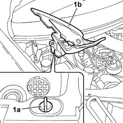
1. Disconnect the bonnet release control cable from the lock.
2. Undo the fixing nuts (2a) and remove the bonnet lock (2b) from the housing.
Disconnect the electrical connector for the bonnet opening switch, incorporated in the actual lock, for the alarm system.
1. Disconnect the electrical connectors for the engine fans.
2. Release the electrical wiring for the engine fans from the retaining springs.
Place the above mentioned electrical wiring to the side.
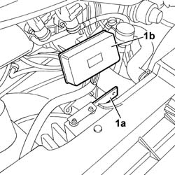
1. Release the control unit (1b), complete with electrical wiring, from the mounting bracket (1a) and place the control unit at the side.
1. Opening the retaining band, disconnect the coolant supply pipe from the expansion tank to the engine radiator, radiator side.
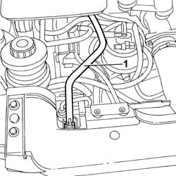
1. Opening the retaining band, disconnect the engine coolant supply pipe from the radiator, radiator side.
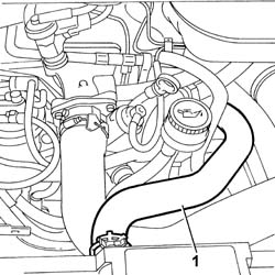
1. Remove the hose (1a) from the air/air heat exchanger (intercooler) to the intake manifold, opening the retaining bands (1b).
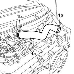
1. Open the retaining band (1a) and release the hose (1b).
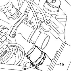
See
1. Position terminals on the coolant pipes.
2. Open the fastenings and prise the coolant pipes off the heat exchanger
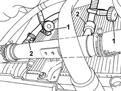
1. Undo the upper retaining bolts for the radiator/fan assembly.
2. Undo retaining nuts (2a) and disconnect the pipe (2b) for the air conditioning unit from the condenser.
3. Disconnect the electrical connection.
Disconnect the lower hose from the air/air heat exchanger.
Disconnect the electrical connection for the linear sensor.
Release the power steering fluid pipes from the bands on the lower crossmember.
4. Remove the radiator-fan-condenser assembly.
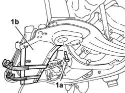
1. Undo the fixing bolts (1a) and remove the lower crossmember (1b).
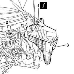
1. Disconnect the electrical connection for the air flow meter.
2. Disconnect the turbocharger flexible air inlet hose.
3. Remove the air filter casing from the housing.
1. Release the air filter casing flexible cold air intake pipe from the support.
2. Undo the fixing nuts and bolt.
3. Remove the mounting bracket complete with mechanical vehicle lifting device.
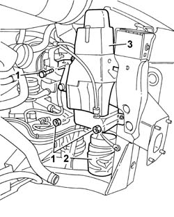
1. Undo the bolt fixing the engine coolant reservoir to the mounting bracket.
2. Disconnect the electrical connection for the engine coolant level sensor.
3. Disconnect the two engine coolant pipes from the rapid connectors.
4. Remove the engine coolant reservoir.
Open the power assisted steering fluid reservoir plug.
Remove the power assisted steering fluid filter from the housing in the reservoir.
Using a syringe, remove the power assisted steering fluid contained in the reservoir and collect it in a special container.
1. Disconnect the two power assisted steering system fluid pipes from the pump.
2. Release the power assisted steering pump fluid reservoir from the mounting and remove it.
1. Undo retaining nuts (1a) and remove the two power assisted steering fluid reservoir mounting brackets.
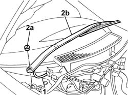
1. Disconnect the screen washer fluid supply pipe from the coupling.
2. Undo the fixing nut (2a) and remove the wiper arm (2b).
Use a suitable tool to extract the wiper arm from the housing.
| Description | Code | Function | |
|---|---|---|---|
| Extractor | Removing wiper arm |
Carry out the same procedure for the remaining wiper arm.
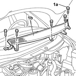
1. Undo the fixing bolts (1a) and remove the protective grille (1b) at the base of the windscreen.
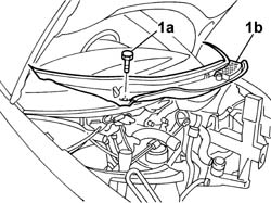
1. Undo the three fixing bolts (1a) and remove the windscreen base trim (1b).
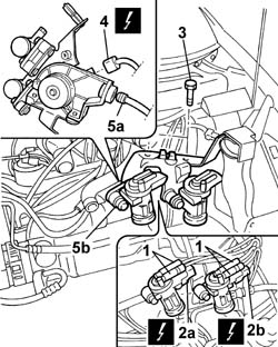
1. Disconnect the vacuum pipes from the solenoid valves.
Before disconnecting them it is advisable to mark the position to prevent reconnecting them in the wrong positions.
2. Disconnect the electrical connections (2a) and (2b).
3. Undo the retaining bolts.
4. Disconnect the electrical connection for the accelerator pedal potentiometer.
5. Release the accelerator control ca ble (5a) from the housing and remove the solenoid valve and accelerator potentiometer assembly (5b).
Op. 5010B18 HEATING VENTILATION UNIT AIR INTAKE - R+R
1. Undo the fixing bolts (1a) and remove the mounting brackets (1b) at the base of the windscreen.
Carry out the same operations for the mounting bracket located on the right side which is not illustrated.
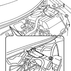
1. Rotate the fastening (1a) and remove the side protection at the base of the windscreen (1b).
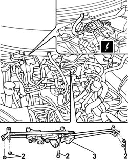
1. Disconnect the electrical connection for the windscreen wiper motor.
Release the fuel pipes from the mounting bracket.
2. Undo the fixing nuts and bolts.
3. Remove the windscreen wiper operating mechanism and motor assembly.
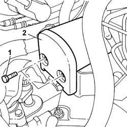
1. Undo the bolts securing the earth.
2. Release and remove the earth on the engine mount.
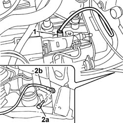
1. Disconnect the electrical connection for the reversing light switch.
2. Undo the fixing bolt (2a) and release the gearbox earth lead (2b) from the bodyshell.
1. Undo the fixing bolts (1a) and remove the protective cover (1b) for the engine management control unit.
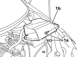
1. Disconnect the engine management unit electrical connections.
2. Undo the bolt and release the earth lead from the gearbox.
3. Disconnect the electrical connection for the ABS control unit.
Release the injection wiring from the retaining bands.
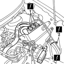
1. Undo the fixing nut (1a) and move the heater plugs control unit (1b) out of the housing.
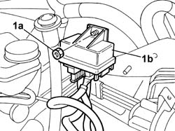
1. Lift up the engine compartment junction unit protective cover.
2. Disconnect the electrical connections from the engine compartment junction unit.
3. Undo the nut (3a) and separate the earth lead (3b) from the attachment on the control unit.
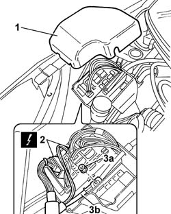
1. Undo the fixing nuts (1a) and disconnect the two pipes (1b) for the air conditioning system from the air conditioning compressor.
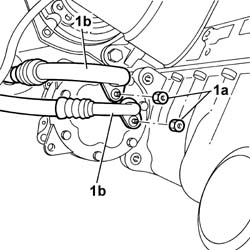
1. Undo the connector (1a) for the power assisted steering fluid pipe, undo the nut (1b) for the bracket and move the power assisted steering fluid pipe (1c) away from the work area.
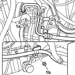
1. Disconnect the two fuel pipes from the rapid connectors.
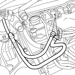
1. Disconnect the two heater supply and return pipes from the rapid connectors.
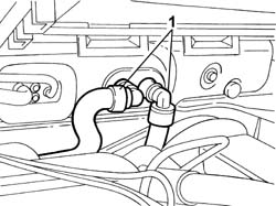
1. Remove the protective cover.
2. Loosen the nut, release the fluid pipe and fold the bracket over downwards.
3. Press and rotate the clutch actuator cylinder in an anti-clockwise direction and remove it.
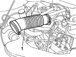
1. Remove the turbocharger flexible air intake hose.
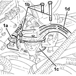
1. Disconnect the gear selector flexib le cable (1a), undo the bolts (1b) and remove the bracket (1c) complete with counter-weight (1d).
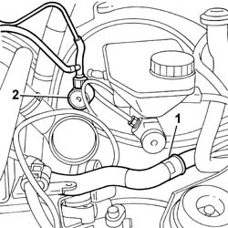
1. Disconnect the additional heater water pipe from the rapid connector.
2. Disconnect the single-acting valve from the brake servo.
Raise the vehicle.
1. Acting on the band (1a) and the fixing nut (1b), remove the heat exchanger rigid air pipe (1c).
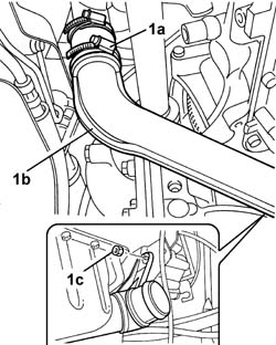
1. Undo the fixing nuts (1a) and separate the exhaust pipe from the manifold (1b).
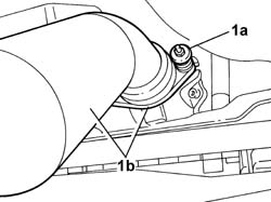
Have a suitable container for collecting the transmission fluid ready.
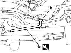
1. Undo the plug (1b), using a suitable spanner (1a), and drain the transmission fluid.
| Description | Code | Function | |
|---|---|---|---|
| 1a | Spanner | Wrench for slackening/tightening differential fluid plug |
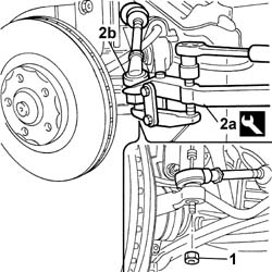
1. Undo the nut fixing the track rod end to the steering knuckle.
2. Extract the track rod end (2b) from the housing in the steering knuckle using the tool (2a).
| Description | Code | Function | |
|---|---|---|---|
| 2a | Head extractor | Ball joint removal |
Carry out the same operations on the remaining head.
1. Undo the bolts fixing the steering knuckle to the shock absorber.
2. Release the inner driveshaft from the housing in the differential.
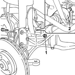
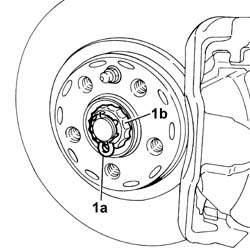
1. Working on the right side of the vehicle, remove the spring (1a), remove the split pin (1b) and undo the nut underneath.
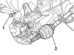
1. Undo the bolts fixing the steering knuckle to the shock absorber.
2. Fold the steering knuckle downwards and release the right driveshaft from the housing.
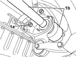
1. Undo the fixing nuts (1a) and remove the intermediate driveshaft and right driveshaft assembly (1b) from the wheel arch.
1. Undo the bolts securing the lower reaction rod.
2. Remove the lower reaction link.
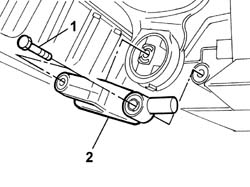
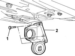
1. Undo the retaining bolts.
2. Remove the intermediate driveshaft support.
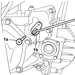
1. Undo the fixing bolt (1a) and remove the reverse gear inhibitor switch (1b).
1. Place the tool for removing the power unit in position.
| Description | Code | Function | |
|---|---|---|---|
| 1 | Hydraulic lift | Power unit support |
2. Fit the tool for the engine mounting brackets
| Description | Code | Function | |
|---|---|---|---|
| 2 | Tool for removing and refitting power unit | Power unit support |
3. Fit the front engine mounting bracket.
| Description | Code | Function | |
|---|---|---|---|
| 3 | Engine mounting bracket | Power unit support |
4. Fit the adaptor on the front engine mounting bracket.
| Description | Code | Function | |
|---|---|---|---|
| 4 | Tool for engine support | Power unit support |
5. Fit the rear engine mounting bracket.
| Description | Code | Function | |
|---|---|---|---|
| 5 | Engine mounting bracket | Power unit support |
Tighten the enigne mounting brackets to the cylinder block/crankcase.
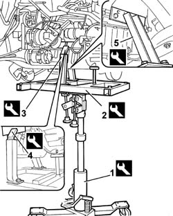
At the same time, lower the hydraulic support and the lift.
1. Undo the fixing bolts (1a) and remove the upper power unit rod (1b).
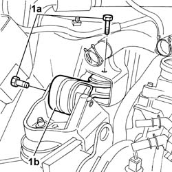
1. Undo the fixing nut and bolt.
2. Remove the timing side rigid power unit support.
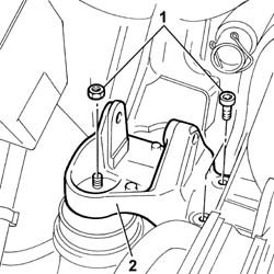
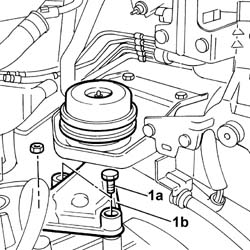
1. Undo the two bolts and the nut (1a) and separate the rigid power unit support (1b) from the gearbox and differential unit.
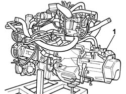
1. Manoeuvre the power unit turning it, then remove it from the engine compartment.
Take the greatest care not to damage parts fitted to the vehicle during engine rotation and removal.
Refitting
Support the power unit by means of a hydraulic lift fitted with the support tool and position the power unit in its compartment on the vehicle.
Take the greatest care not to damage parts fitted to the vehicle during engine installation.
Fit the gearbox side rigid power unit support and tighten the fixing nuts and bolts.
| da Nm | Fastening | Component | dia |
|---|---|---|---|
| 4.5 | Bolt | POWER UNIT QUICK MOUNT, GEARBOX SIDE |
| da Nm | Fastening | Component | dia |
|---|---|---|---|
| 4.5 | Nut | POWER UNIT QUICK MOUNT, GEARBOX SIDE |
Fit the timing side rigid power unit support and tighten the fastenings to torque.
| da Nm | Fastening | Component | dia |
|---|---|---|---|
| 6.0 | Bolt | POWER UNIT QUICK MOUNT, TIMING SIDE |
| da Nm | Fastening | Component | dia |
|---|---|---|---|
| 4.5 | Nut | TIMING SIDE RIGID MOUNT FLEXIBLE BLOCK |
Position the power unit upper rod and tighten the retaining bolts.
| da Nm | Fastening | Component | dia |
|---|---|---|---|
| 5.0 | Bolt | UPPER POWER UNIT LINK |
Remove the tool fitted previously for supporting and removing the unit from the power unit.
| Description | Code | Function | |
|---|---|---|---|
| Hydraulic lift | Power unit support |
| Description | Code | Function | |
|---|---|---|---|
| Tool for removing and refitting power unit | Power unit support |
| Description | Code | Function | |
|---|---|---|---|
| Engine mounting bracket | Power unit support |
| Description | Code | Function | |
|---|---|---|---|
| Tool for engine support | Power unit support |
| Description | Code | Function | |
|---|---|---|---|
| Engine mounting bracket | Power unit support |
Fit the reverse gear inhibitor switch and tighten the fixing bolt.
Fit the intermediate driveshaft support and tighten the fixing bolts.
| da Nm | Fastening | Component | dia |
|---|---|---|---|
| 4.5 | Bolt | INTERMEDIATE DRIVESHAFT MOUNT |
Fit the intermediate drive shaft with drive shaft and tighten the bolts securing it to the intermediate drive shaft.
| da Nm | Fastening | Component | dia |
|---|---|---|---|
| 1.75 | Bolt | INTERMEDIATE DRIVE SHAFT |
Fit the power unit lower rod and tighten the retaining bolts.
| da Nm | Fastening | Component | dia |
|---|---|---|---|
| 9 | Bolt | LOWER LINK SECURING THE POWER UNIT TO THE BODY |
| da Nm | Fastening | Component | dia |
|---|---|---|---|
| 6.5 | Bolt | LOWER LINK SECURING THE POWER UNIT TO THE MOUNT |
Place the steering knuckle in position and tighten the bolts fixing it to the shock absorber.
| Value daNm | Fastening | Component | dia | |
|---|---|---|---|---|
| (Shock absorber) 9 | Bolts | FRONT HUB STRUT |
Tighten the nut fixing the drive shaft to the wheel hub.
| Value daNm | Fastening | Component | dia | |
|---|---|---|---|---|
| 10 | Nut | FRONT HUBS COMPLETE WITH BEARING |
Fit the split pin and position the spring.
Place the inner driveshaft in position on the differential and in the housing in the wheel hub.
Tighten the bolts securing the steering knuckle to the shock absorber to torque.
| Value daNm | Fastening | Component | dia | |
|---|---|---|---|---|
| (Shock absorber) 9 | Bolts | FRONT HUB STRUT |
Tighten the nut fixing the drive shaft to the wheel hub.
| Value daNm | Fastening | Component | dia | |
|---|---|---|---|---|
| 10 | Nut | FRONT HUBS COMPLETE WITH BEARING |
Fit the track rod ends in the steering knuckle and tighten the fixing nuts to torque.
| Value daNm | Fastening | Component | dia | |
|---|---|---|---|---|
| (steering knuckle) 4 | Nut | ADJUSTABLE STEERINGI LINK JOINTS (C-S) |
Tighten the plug in the gearbox-differential housing to torque.
| Value daNm | Fastening | Component | dia | |
|---|---|---|---|---|
| 3.5 | Plug | GEAR CASING PADS |
Tighten the nuts securing the exhaust manifold to the pipe.
Fit the heat exchanger rigid air pipe and tighten the fixing nut and connect the band.
Connect the single-acting valve to the brake servo.
Connect the additional heater water pipe to the rapid connector.
Fit the selector unit and attachments and tighten the fixing bolts.
Connect the end of the gear selector flexible cable.
Fit the turbochrger flexible air inlet hose.
Fit the clutch actuator cylinder and tighten the retaining bolts.
Reposition the fluid pipe and fit the protective cover.
Connect the water supply and return pipes to the heater to the rapid connectors.
Place the power assisted steering fluid pipe in position and tighten the pipe connector.
| Value daNm | Fastening | Component | dia | |
|---|---|---|---|---|
| 2.5 | Nut | PIPE BTWN PUMP + POWER STEERING BOX |
Connect the two fuel pipes to the rapid connectors.
Connect the air conditioning system pipes to the compressor and tighten the fixing nuts.
| da Nm | Fastening | Component | dia |
|---|---|---|---|
| 2.5 | Bolt | COMPRESSOR PIPES |
Connect the earth lead to the junction unit.
Connect the electrical connections to the engine compartment junction unit.
Fit the engine compartment junction unit protective cover.
Fit the heater plugs plug control unit in its seat on the bracket and tighten the retaining nut.
Position the injection wiring and connect the electrical connections.
Tighten the bolt for the earth lead from the gearbox.
Connect the electrical connection for the ABS control unit.
Fit the engine management control unit protective cover.
Connect the electrical connection for the reversing light switch.
Connect the gearbox earth lead to the bodyshell.
Fit the windscreen wiper operating mechanism and motor assembly.
Connect the electrical connection for the windscreen wiper motor.
Fit the side protection at the base of the windscreen
Fit the mounting brackets for the trim at the base of the windscreen.
Carry out the same operations for the mounting bracket located on the right side.
See
Op. 5010B18 CLIMATE CONTROL UNIT AIR INTAKE - R.R.
Fit the accelerator potentiometer and solenoid valve assembly.
Connect the accelerator control cable
Connect the accelerator pedal potentiometer electrical connection and tighten the fixing bolts.
Connect the electrical connections for the EGR solenoid valve and the supercharging pressure solenoid valve (waste gate).
Connect the vacuum pipes to the solenoid valves.
Fit the trim at the base of the windscreen.
Fit the protective grille for the trim at the base of the windscreen
Fit the wiper arms and tighten the retaining nuts.
Connect the screen washer fluid supply pipe.
Fit the two power assisted steering fluid reservoir mounting brackets.
Fit the earth on the engine mount and tighten the retaining bolts.
Fit the power assisted steering fluid reservoir in the mounting.
Connect the two power assisted steering system fluid pipes.
Fit the engine coolant reservoir.
Connect the two engine coolant pipes to the rapid connectors.
Connect the electrical connection for the engine coolant level sensor.
Tighten the bolt fixing the engine coolant reservoir to the mounting bracket.
Fit the mounting bracket complete with mechanical vehicle lifting device and tighten the nuts and bolts.
Remove the air filter casing from the housing.
Connect the turbocharger flexible air inlet hose.
Connect the electrical connection for the air flow meter.
Fit the lower crossmember and tighten the fixing bolts.
Fit the radiator-fan-condenser assembly.
Connect the electrical connection for the linear sensor.
Connect the lower hose to the air/air heat exchanger.
Connect the condenser air conditioning assembly pipe and tighten the fixing nuts.
Tighten the upper retaining bolts for the radiator/fan assembly.
Fit the air/air heat exchanger (intercooler) hose to the intake manifold.
Connect the sleeve from heat exchanger to throttle body.
Connect the pipes to the FAP system heat exchanger and remove the terminals.
See
Connect the radiator coolant supply pipe.
Connect the engine coolant supply pipe from the expansion tanke to the engine radiator.
Fit the control unit complete with mounting bracket and wiring.
Connect the electrical connectors for the engine fans.
Secure the electrical wiring for the engine fans to the retaining springs.
Connect the electrical connector for the bonnet opening switch, incorporated in the actual lock, for the alarm system.
Fit the bonnet lock.
Connect the bonnet release control cable to the lock.
Carry out the bonnet lock adjustment: see op. 7025A10
Fit the lower crossmember and tighten the fixing bolts.
Fit the upper front crossmember and tighten the fixing nuts.
Using a new retaining band, fasten the headlamp washer fluid supply pipe to the front crossmember
See
Op. 5540B78 LEFT FRONT LIGHT CLUSTER WITH DIRECTION INDICATOR AND FOG LIGHT - R.R.
See
Op. 5540B79 RIGHT FRONT LIGHT CLUSTER WITH DIRECTION INDICATOR AND FOG LIGHT - R.R.
See
See
Op. 7055B91 RIGHT FRONT WHEEL ARCH LINER - R.R.
See
Op. 7055B91 RIGHT FRONT WHEEL ARCH LINER - R.R.
See
Op. 4450B12 FRONT WHEELS (TWO) - R+R
See
Op. 7055B54 UNDER ENGINE PROTECTION/GUARD - R.R.
See
Op. 0010T84 COOLANT FOR AIR CONDITIONING SYSTEM - DEHYDRATE AND REPRESSURIZE
Bleed the air from the engine coolant system.
See
Op. 0010T21 ENGINE COOLANT - CHECK DENSITY AND CHANGE, IF NECESSARY
See
Parts & tools for this job Staging For 2002 Fiat Ulysse
- PARTClutch kitSearch: Fiat Ulysse 2002 clutch kit
- TOOLClutch alignment toolSearch: clutch alignment tool
- FLUIDGear oilSearch: Fiat Ulysse manual gearbox oil
Links open Amazon search results in a new tab. As an Amazon Associate I earn from qualifying purchases.