
Single cylinder head - r.r. and replace gasket
- Make
- Fiat
- Model
- Ulysse Factory Service Manual
- Year
- 2002–2010
- Section
- Cylinder head/s › Single cylinder head - r.r. and replace gasket
SINGLE CYLINDER HEAD - R.R. AND REPLACE GASKET
- Operation not available.
Removing
Op. 5530B56 BATTERY DRIP TRAY COVER - R.R.
Disconnect the negative battery terminal.
Op. 5010B18 HEATING VENTILATION UNIT AIR INTAKE - R+R
See descriptions
See descriptions
Op. 7055B54 UNDER ENGINE PROTECTION/GUARD - R.R.
Op. 4450B04 RIGHT FRONT WHEEL - R.R
Op. 4410D16 BRACKET (ONE) RETAINING CHASSIS TO BODY - R R
< R1 > Right side, front
See descriptions
See descriptions
See descriptions
See descriptions
See descriptions
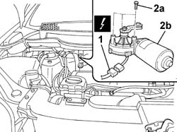
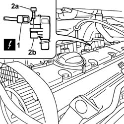
1. Disconnect the electrical connection for the windscreen wiper motor.
2. Undo the retaining bolts (2a) and remove windscreen wiper motor (2b).
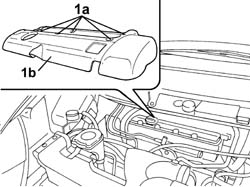
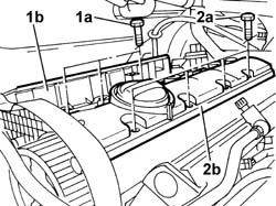
1. Turn retaining bolts (1a) through 90° and remove coil cover (1b).
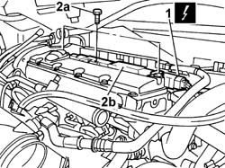
1. Disconnect the electrical connections for the coils.
2. Undo retaining bolts (2a) and remove coils (2b).
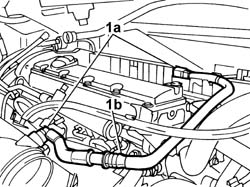
1. Disconnect quick-release connectors (1a) from the oil vapour separator and from the rigid air intake sleeve on the throttle body and place piping (1b) to one side.
1. Disconnect the electrical connection for the cam angle sensor.
2. Undo the fixing bolts (2a) and remove the cam angle sensor (2b).
1. Undo retaining bolts (1a) and remove the exhaust side oil cam cover with built-in oil separator cover (1b).
2. Undo retaining bolts (2a) and remove the intake side cam cover (1b).
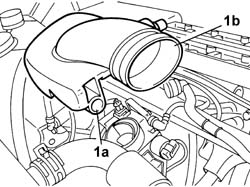
1. Loosen the retaining band through hole (1a) and remove the rigid air intake sleeve from throttle body (1b)
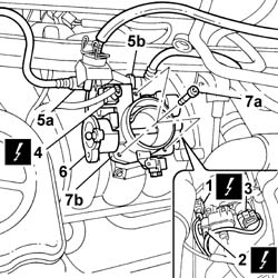
1. Disconnect the electrical connection for the air temperature sensor.
2. Disconnect the electrical connection for the throttle position sensor.
3. Disconnect the electrical connection from the engine idle speed adjustment actuator.
4. Disconnect the electrical connection for the resistance pad heater.
5. Disconnect the quick-release fitting for fuel vapour return pipe (5a) and the quick-release fitting of the pipe connected to oil vapour sepator (5b).
6. Prise out the accelerator wire and place to one side.
7. Undo retaining bolts (7a) and remove the throttle body (7b)
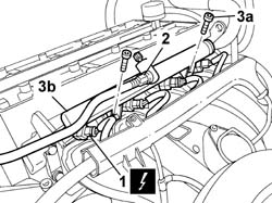
1. Disconnect the electrical connections for the injectors.
2. Disconnect the rapid connector for the fuel supply pipe to the single fuel manifold pipe.
3. Undo retaining bolts (3a) and remove the single injection holder fuel manifold with injectors (3b).
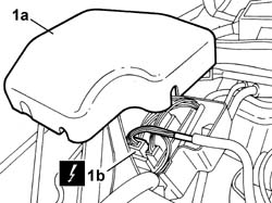
1. Remove the cover from right front side fuse carrier case (1a) and disconnect the electrical connection from wiring (1b).
1. Disconnect the electrical connection for the EGR modulator solenoid valve.
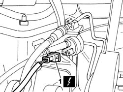
1. Disconnect the electrical connection (1a) from the engine oil temperature sensor and release the wiring (1b) from the plastic retainingn clip.
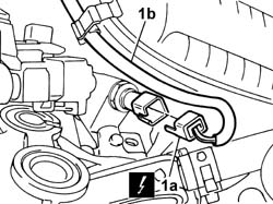
1. Disconnect the electrical connection for the air pressure sensor.
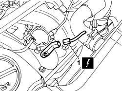
1. Undo bolts (1a) retaining wiring channel and place to one side (1b).
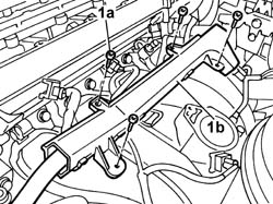
1. Undo bands (1a) using a special tool, release the brake servo vacuum pipe from plastic retaining clip (1b) and place coolant sleeve (1c) to one side.
| Description | Code | Function | |
|---|---|---|---|
| Caliper | Removing bands |
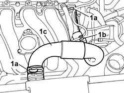
1. Disconnect quick-release fitting (1a) and place brake servo vacuum pipe to one side.
2. Release the retaining springs (2a) and move pipe (2b) aside.
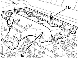
3. Undo retaining bolts (3a) and remove the air intake manifold (3b).
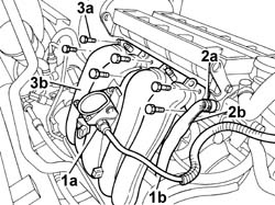
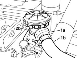
1. Disconnect quick-release fitting (1a) from the cut-off valve and move sleeve (1b) to one side.
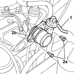
2. Undo retaining bolts (2a) and remove cut-off valve (2c).
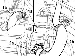
1. Remove retaining band (1a) using the special tool and move sleeve (1b) aside.
2. Remove retaining band (2a) using the special tool and move sleeve (2b) aside.
| Description | Code | Function | |
|---|---|---|---|
| Caliper | Removing bands |
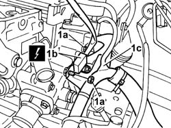
1. Unscrew retaining nuts (1a), move condenser (1b) aside and move anchorage bracket with wiring (1c).
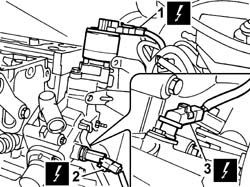
1. Disconnect the electrical connection for the EGR solenoid valve.
2. Disconnect the electrical connection for the air temperature sensor.
3. Disconnect the electrical connection for the rpm sensor.
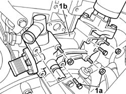
1. Undo retaining bolts and nuts (1a) and remove the thermostat unit assembly (1b).
Raise the vehicle.
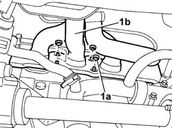
1. Undo retaining nuts (1a) and separate the exhaust manifold (1b) at the rear to release from the studs.
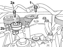
1. Unscrew the bolt securing the rigid timing side mounting that is engaged in the cylinder head.
2. Undo retaining bolt (2a) and remove timing belt mobile tensioner (2b).
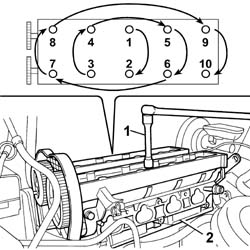
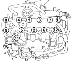
1. Unscrew the bolts securing the cylinder head in the order shown in the figure.
2. Remove the single cylinder head with the aid of a second operator.
1. Remove the gasket.
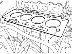
Refitting
Replace the gasket with a one of the same type.
Lubricate the bolt thread and mating surface.
1. Position the single cylinder head with the aid of a second operator.
2. Tighten the cylinder head bolts to the recommended torque in the order indicated, using an angular tightening tool.
| Value daNm | Fastening | Component | dia | |
|---|---|---|---|---|
| 1,5 + 5,0 -360° +2.0+ 270° | Bolt | CYLINDER HEAD |
| Description | Code | Function | |
|---|---|---|---|
| Torque wrench | Angular tightening |
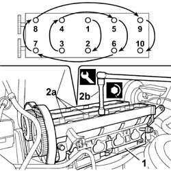
Fit the mobile timing belt tensioner and screw in the retaining bolt without tightening it.
Tighten the bolt securing the rigid timing side mounting that is engaged in the cylinder head.
Fit the exhaust manifold and tighten the retaining nuts to torque.
| Value daNm | Fastening | Component | dia | |
|---|---|---|---|---|
| 3,5 | Nut | EXHAUST MANIFOLD/S |
Fit the thermostat unit.
Tighten the nuts and bolts securing the thermostat mount to the specified torque.
Connect the electrical connection for the rpm sensor.
Connect the electrical connection for the coolant temperature sensor.
Connect the electrical connection for the EGR solenoid valve.
Fit the bracket anchoring the wiring and tighten the retaining bolts.
Fit the sleeves on the thermostat mount and refasten by doing up the bands with the special tool.
| Description | Code | Function | |
|---|---|---|---|
| Caliper | Removing bands |
Fit the cut-off valve and tighten the retaining bolts. Connect the quick-release fitting of the sleeve removed previously.
Position the intake manifold and tighten the fixing bolts to torque.
| Value daNm | Fastening | Component | dia | |
|---|---|---|---|---|
| 1 | Bolt | INLET MANIFOLD |
Connect the brake servo vacuum pipe rapid connector.
Fit the exhaust gas recirculation pipe and refasten.
Fit the coolant sleeve.
Refasten the sleeve using the special tool.
| Description | Code | Function | |
|---|---|---|---|
| Caliper | Removing bands |
Place the wiring duct in position and tighten the fixing bolts.
Connect the electrical connection for the air pressure sensor.
Connect the electrical connection for the engine oil temperature sensor and fasten the wiring using the plastic retaining clip.
Connect the electrical connection for the EGR modulator solenoid valve.
Connect the electrical connection for the wiring and fit the fuse box cover, right front.
- Fit the single fuel manifold complete with injectors and tighten the fixing bolts.
Connect the rapid connector for the fuel supply pipe to the single fuel manifold.
Connect the electrical connections for the injectors.
Position the throttle body and tighten the retaining bolts.
Fit the accelerator control cable.
Connect the rapid connector for the pipe coming from the oil vapour separator and the rapid connector for the fuel vapour return pipe.
Connect the electrical connection for the resistive pad heater.
Connect the electrical connection for the engine idle speed adjustment actuator.
Connect the electrical connection for the throttle position sensor.
Connect the electrical connection for the air temperature sensor.
Fit the rigid air intake sleeve to the throttle body and refasten.
1. Fit the cam cover with built-in oil vapour separator (1a) and tighten retaining bolts (1b) to torque in the order shown in the figure.
| Value daNm | Fastening | Component | dia | |
|---|---|---|---|---|
| 0.5 + 1.1 | Bolt | TAPPET COVER with built in oil vapour separator |
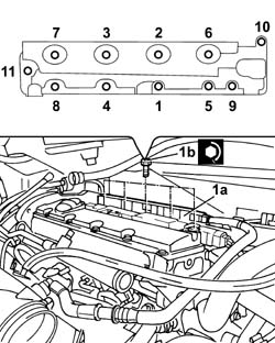
1. Fit the left cam cover (1a) and tighten cam cover retaining bolts (1b) in the order shown in the figure.
| Value daNm | Fastening | Component | dia | |
|---|---|---|---|---|
| 0.5 + 1.1 | Bolt | Left TAPPET COVER - R.R. and Replace gasket |
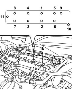
Fit the cam angle sensor and tighten the fixing bolt.
Connect the electrical connection for the cam angle sensor.
Fit the pipe and connect the quick-release fittings to the oil vapour separator and on the rigid air intake sleeve to the throttle body.
Fit the coils and tighten the fixing bolts.
Connect the electrical connection for the coils.
Fit the coil cover and rotate the fastening pins through 90° to secure it.
Fit the windscreen wiper motor and tighten the fixing bolts.
Connect the electrical connection for the windscreen wiper motor.
See descriptions
See descriptions
See descriptions
See descriptions
See descriptions
Op. 4410D16 BRACKET (ONE) RETAINING CHASSIS TO BODY - R R
< R1 > Right side, front
Op. 7055B91 RIGHT FRONT WHEEL ARCH LINER - R.R.
Op. 4450B04 RIGHT FRONT WHEEL - R.R
Op. 7055B54 UNDER ENGINE PROTECTION/GUARD - R.R.
See descriptions
Op. 0010T21 ENGINE COOLANT - CHECK DENSITY AND CHANGE, IF NECESSARY
See descriptions
See descriptions
Op. 5010B18 HEATING VENTILATION UNIT AIR INTAKE - R+R
Op. 0010T11 ENGINE OIL - CHECK LEVEL AND TOP UP, IF NECESSARY
Connect the negative battery terminal.
Op. 5530B56 BATTERY DRIP TRAY COVER - R.R.
Removing
Op. 4450B04 RIGHT FRONT WHEEL - R.R
Op. 7055B91 RIGHT FRONT WHEEL ARCH LINER - R.R.
Op. 7055B54 UNDER ENGINE PROTECTION/GUARD - R.R.
See descriptions
Op. 5530B56 BATTERY DRIP TRAY COVER - R.R.
Op. 5010B18 HEATING VENTILATION UNIT AIR INTAKE - R+R
Op. 5050B34 WINDSCREEN WIPER ARM/S COMPLETE WITH BLADE - R+R
< R1 > [both]
Op. 7055A18 L/H OR R/H SIDE RUBBING STRIP (ONE) FOR FRONT DOOR - R+R
Op. 5050B38 WINDSCREEN WIPER ASSEMBLY - R+R OR REPAIR
See descriptions
See descriptions
See descriptions
See descriptions
See descriptions
See descriptions
See descriptions
Fit the timing side power unit rigid mount and tighten the bolts.
See descriptions
See descriptions
See descriptions
1. Disconnect the electrical connection for the cam angle sensor.
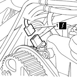
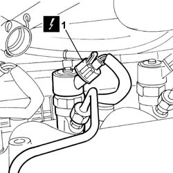
Carry out the same operation on all the injectors
1. Disconnect the electrical connection for the injector.
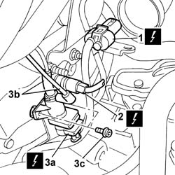
1. Disconnect the electrical connection for the glow plug wiring.
2. Disconnect the electrical connection for the engine coolant temperature sensor.
3. Disconnect electrical connection (3a), disconnect vacuum pipe (3b) and unscrew bolts (3c), remove intake manifold actuator control solenoid.
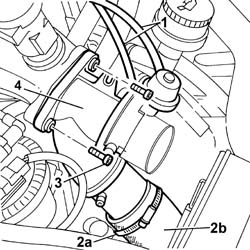
1. Disconnect vacuum pipes.
2. Open the retaining band (2a) and release air sleeve (1b).
3. Undo the bolts securing the throttle body.
4. Remove the throttle body.
1. Open the securing band (1a) using special pliers and destructive band (1b).
2. Remove the oil vapour pipe.
| Description | Code | Function | |
|---|---|---|---|
| Caliper | Open the retaining bands |
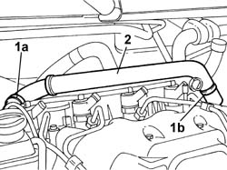
See descriptions
1. Open bands (1a), disconnect oil vapour pipe (1b) and move out of the working area.
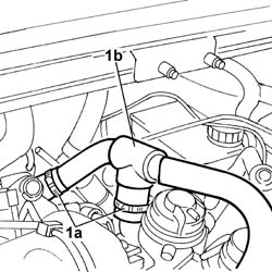
Position a suitable container for collecting the coolant.
1. Open bands (1a) using special pliers, move coolant sleeves (1b) out of the working area and recover the coolant.
2. Undo bolt (2a) ande move the oil dipstick (2b) aside.
| Description | Code | Function | |
|---|---|---|---|
| Caliper | Open the retaining bands |
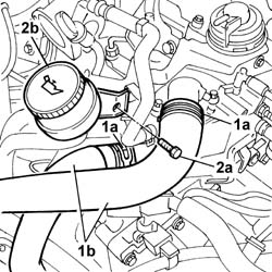
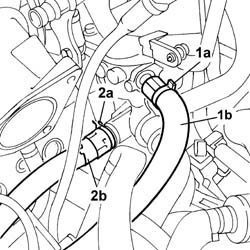
1. Open the securing band (1a) using special pliers and move aside pipe (1b).
2. Undo clip (2a) and disconnect pipe (2b) from the thermostat.
| Description | Code | Function | |
|---|---|---|---|
| Caliper | Open the retaining bands |
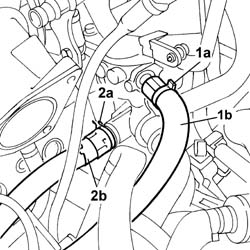
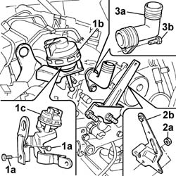
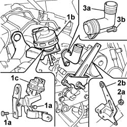
1. Undo bolts (1a), release head (1b) and remove Swirl valve (1c).
2. Undo nuts (2a), remove the mounting bracket (2b) and release from clips.
3. Undo bolt (3a) and remove the fitting (3b).
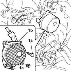
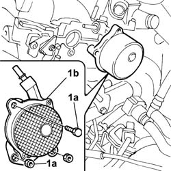
1. Undo bolt and nuts (1a) and remove the vacuum pump (1b).
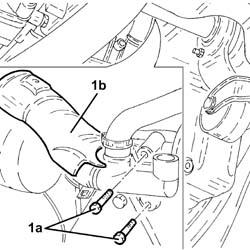
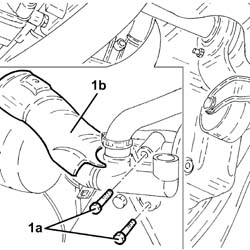
1. Unscrew bolts (1a) securing the delivery pipe to the water pump and remove pipe protection (1b).
1. Open the securing band (1a) using special pliers and disconnect coolant pipe (1b).
| Description | Code | Function | |
|---|---|---|---|
| Caliper | Open the retaining bands |
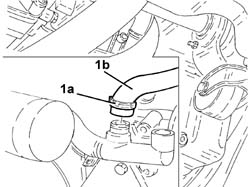
1. Open the securing band (1a) using special pliers and remove the connector connecting the coolant pipes to the water pump (1b).
| Description | Code | Function | |
|---|---|---|---|
| Caliper | Open the retaining bands |
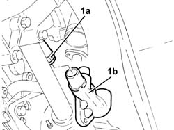
1. Disconnect the gear selector flexible cable (1a), undo the bolts (1b) and remove the bracket (1c) complete with counter-weight (1d).
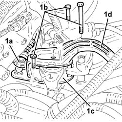
1. Undo the connector (1a) and disconnect the oil delivery pipe to the turbocharger from the engine block.
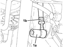
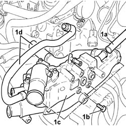
1. Disconnect pipe (1a), undo the bolts (1b) and remove the thermostat (1c) complete with pipes (1d).
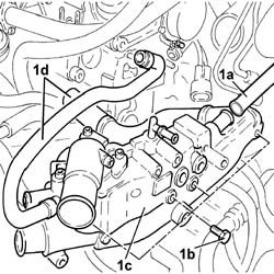
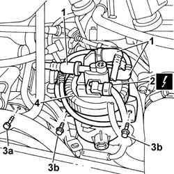
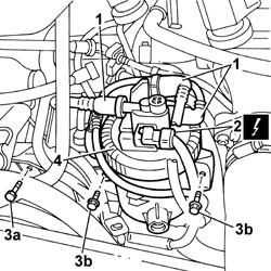
1. Undo the quick-release fittings and disconnect the fuel pipes
2. Disconnect the electrical connection.
3. Undo bolt (3a) securing the wiring channel and move out of the working area. Unscrew bolts (3b) securing the fuel filter.
4. Remove the fuel filter assembly.
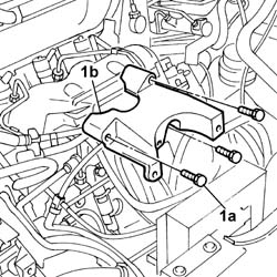
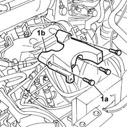
1. Undo bolts (1a) and remove the fuel filter mount (1b).
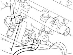
1. Disconnect the quick-release connectors for the fuel pipes.
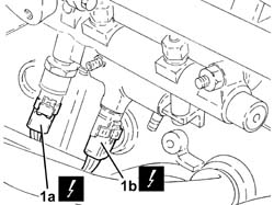
1. Disconnect the electrical connection of fuel pressure sensor (1a) and the electrical connection of fuel temperature sensor (1b).
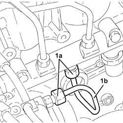
1. Undo the connectors (1a) and remove the rigid fuel supply pipe for the single rigid fuel delivery pipe (1b).
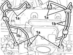
1. Undo the connectors (1a) and disconnect the rigid supply pipes from the single fuel supply pipe to the injectors (1b).
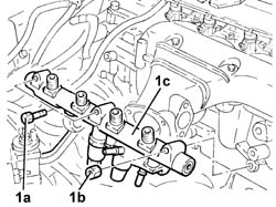
1. Undo bolts (1a) and nut (1b) and remove the single fuel manifold pipe complete with sensors (1c).
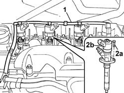
1. Disconnect the fuel return pipe from the injectors and move outside the working area.
2. Undo bolts (2a) and remove injector (2b) using the appropriate tool.
Carry out the same operation on all the injectors
| Description | Code | Function | |
|---|---|---|---|
| Extractor | Injector extractor |
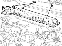
1. Undo bolts (1a) and remove the oil cover/separator (1b).
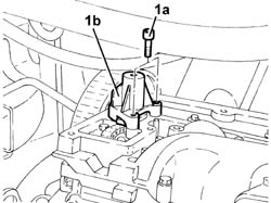
1. Undo bolts (1a) and remove the camshaft drive chain pretensioner (1b).
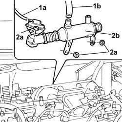
1. Disconnect pipe (1a) from the EGR valve and pipe (1b) from the EGR valve heat exchanger.
2. Undo nuts (2a) and remove the EGR valve - heat exchanger assembly (2b).
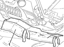
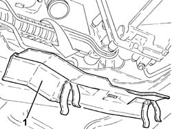
1. Remove the heat shield protection from the steering box.
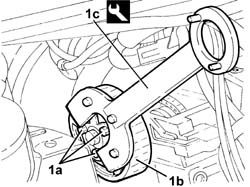
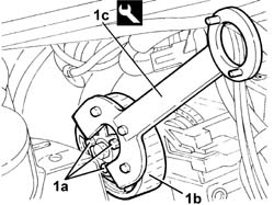
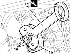
1. Loosen bolts (1a) securing the toothed driven pulley and flange (1b) using tool (1c) for counter-torque.
| Description | Code | Function | |
|---|---|---|---|
| 1c | Counter-torque | Counter-torque for exhaust side camshaft toothed driven pulley |
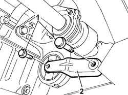
1. Undo the bolts fixing the reaction rod to the intermediate driveshaft support and to the suspension frame.
2. Remove the power unit lower reaction rod.
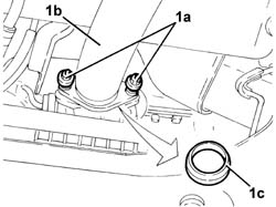
1. Undo bolts (1a) and move exhaust pipe (1b) away from the flange and recover gasket (1c).
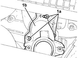
1. Undo bolts (1a) and remove the turbocharger exhaust flange (1b).
1. Undo bolts (1a) and move the oil outlet pipe from the turbocharger (1b) out of the way.
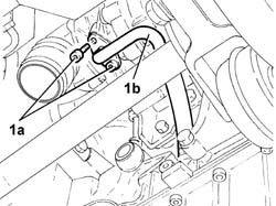
1. Undo bolt (1a) and retaining bolts (1b) and remove turbocharger mount (1c).
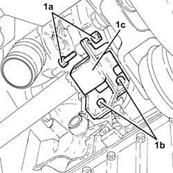
1. Undo exhaust manifold nuts (1b), recover spacers (1b) and release the manifold from the studs.
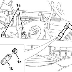
1. Undo bolts (1a) and studs (1b) and remove the single cylinder head extension (1c).
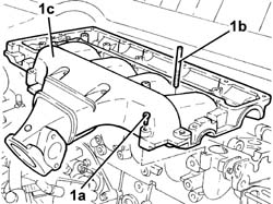
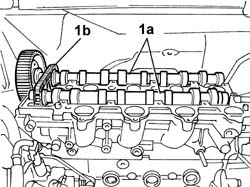
1. Remove camshafts (1a) complete with chain (1b).
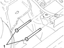
1. Undo the side bolts securing the engine mount to the cylinder head.
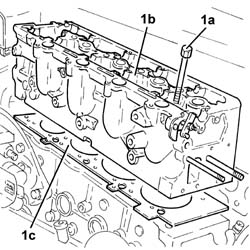
1. Undo bolts (1a) and remove cylinder head (1b) and gasket (1c).
Refitting
1. Measure piston projection (1a) in two places 180° apart on the piston pin centre line using tool (1b) and take the average of the two values measured for each piston.
| Description | Code | Function | |
|---|---|---|---|
| 1b | Dial gauge support | Projection from cylinder head support plane |
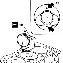
1. Select the correct size cylinder head gasket depending on the maximum average protrusions for each individual piston.
the difference between the minimum and maximum values should not be more than 0.07 mm.
Select a new cylinder head gasket on the basis of the specified values.
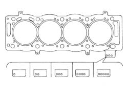
Keep the gasket sealed in its plastic bag and do not remove from its protection until ready to fit.
Do not lubricate the gasket or contaminate with oil or grease.
1. Refit cylinder head gasket (1a) in its seat and centre on locating pins (1b).
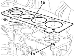
Position the cylinder head on the cylinder block/crankcase.
1. Tighten the bolts securing the cylinder head to the cylinder block to the recommended torque following the order illustrated and using the angular tightening tool.
| Description | Code | Function | |
|---|---|---|---|
| Torque wrench | Cylinder head bolts angular tightening |
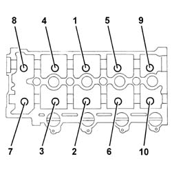
| Value daNm | Fastening | Component | dia | |
|---|---|---|---|---|
| 2 | Pretightening, Bolt | CYLINDER HEAD |
| Value daNm | Fastening | Component | dia | |
|---|---|---|---|---|
| 6 | Tightening, Bolt | CYLINDER HEAD |
| Value daNm | Fastening | Component | dia | |
|---|---|---|---|---|
| 220° +/- 5° | Angular tightening, Bolt | CYLINDER HEAD |
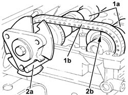
1. Position camshafts (1a) complete with chain (1b).
2. Use an 8 mm calibrated pin (2a) to adjust the exhaust side camshaft timing and turn notch (2b) upward to adjust the inlet side camshaft timing.
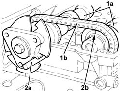
Apply silicone sealant to the mating surface between the cylinder head extension and cylinder head.
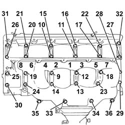
1. Fit the single cylinder head extension and tighten the bolts to the specified torque in the tightening order shown.
references 1 to 8 indicate the studs and references 9 to 36 indicate the bolts.
| Value daNm | Fastening | Component | dia | |
|---|---|---|---|---|
| (Cylinder head extension) 1 | Stud | CYLINDER HEAD EXTENSION |
| Value daNm | Fastening | Component | dia | |
|---|---|---|---|---|
| (Cylinder head extension) 0,5 | Pretightening, Bolt | CYLINDER HEAD EXTENSION |
| Value daNm | Fastening | Component | dia | |
|---|---|---|---|---|
| (Cylinder head extension) 1 | Tightening, Bolt | CYLINDER HEAD EXTENSION |
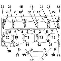
Tighten the side bolts securing the engine mount to the cylinder head and tighten to the specified torque.
Fit the exhaust manifold in position with the spacers and tighten the lower fixing nuts checking the torque.
Fit the turbocharger mount in place and tighten the fastenings.
Fit the oil outlet pipe from the turbocharger and tighten the fixing bolts.
Position the exhaust pipe on the flange after fitting the steel gasket, screw in the bolts and tighten to torque.
Fit the lower reaction link, screw in the bolts and tighten to torque.
Position the heat shield protection on the steering box.
Fit the EGR valve - heat exchanger in its seat, tighten the nuts and connect the pipes to the inlets/outlets on the assembly.
Position the camshaft drive chain tensioner and tighten the bolts.
1. Position the oil vapour cover/separator in its seat and screw in the bolts. Tighten to the required torque and follow the tightening order indicated.
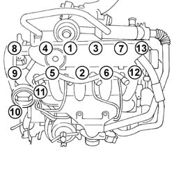
Remove the 8 mm calibrated pin.
Unscrew and remove the exhaust end camshaft flange using a tool for counter-torque.
| Description | Code | Function | |
|---|---|---|---|
| Counter-torque | Counter-torque |
Remove the exhaust camshaft oil seal. This operation is destructive for the oil seal, but take care not to damage the oil seal seat.
1. Fit a new exhaust end camshaft oil seal (1a) using fitting tool (1b).
| Description | Code | Function | |
|---|---|---|---|
| 1b | Fitting tool | Fit the oil seal on the camshaft |
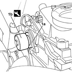
1. Fit flange (1a) into its seat on the exhaust end camshaft and tighten bolt (1b). Tighten to the specified torque using tool (1c) for counter-torque.
| Description | Code | Function | |
|---|---|---|---|
| 1c | Counter-torque | Counter-torque |
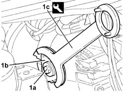
1. Fit toothed driven pulley (1a) into its proper seat on the exhaust end camshaft and tighten bolts (1b). Tighten to the specified torque using tool (1c) for counter-torque.
| Description | Code | Function | |
|---|---|---|---|
| 1c | Counter-torque | Counter-torque for exhaust side camshaft toothed driven pulley |
Fit the injectors in place and tighten the fixing nut checking the torque.
Connect the fuel return pipe to the injectors.
Position the single fuel manifold pipe complete with sensors and tighten the fixing nuts.
Fit a new rigid pipe carrying fuel from the pressure pump to the single fuel manifold pipe and tighten the connectors to the specified torque.
Fit the new rigid fuel delivery pipes from the single fuel manifold to individual injectors and tighten the connectors to the specified torque.
Connect the fuel pressure sensor electrical sensor and the fuel temperature sensor electrical connection located on the single fuel manifold pipe.
Connect the fuel pipe quick-release fittings to the single fuel manifold pipe.
Place the fuel filter mounting in position and tighten the fixing bolts.
Place the trim in position and tighten the fixing bolts.
Connect the fuel pipe rapid connectors to the filter.
Connect the electrical connection for the fuel filter sensor.
Fit the thermostat unit in place and tighten the fixing bolt checking the torque.
Connect the pipes to the thermostat and renew the collars.
Tighten the connector and connect the oil delivery pipe to the turbocharger to the engine block.
Fit the gear selection and engagement bracket in its seat together with the counterweight and tighten the bolts.
Connect the gear selection cable to the bracket.
Position the coolant pipe connector to the water pump and connect the sleeves.
Tighten the bolts fixing the connector to the crankcase.
Do up the sleeve collars using the appropriate tool.
| Description | Code | Function | |
|---|---|---|---|
| Caliper | Open the retaining bands |
Fit the protection for the water delivery pipe to the water pump.
Fit the vacuum pump and tighten the nuts and bolts.
Position the oil vapour recovery fitting and tighten the bolt.
Fit the Swirl valve.
Tighten the bolts and secure the ball joint in its seat.
Fit the water/oil heat exchanger pipes to the thermostat and do up the fastenings.
Fit both coolant sleeves to the thermostat and renew the collars.
| Description | Code | Function | |
|---|---|---|---|
| Caliper | Open the retaining bands |
Fit the oil filler pipe and tighten the bolt.
Fit the oil vapour pipes and renew the retaining bands.
| Description | Code | Function | |
|---|---|---|---|
| Caliper | Open the retaining bands |
See descriptions
Fit the throttle body using the bolts and connect the vacuum pipes to the valves on the throttle body. Fit the air sleeve and renew the collar.
Connect the electrical connection for the heater plug wiring.
Connect the electrical connection for the engine coolant level sensor.
Fit the intake manifold actuator control solenoid and tighten the bolts.
Connect the vacuum pipes to the intake manifold actuator solenoid.
Connect the electrical connections for the injectors.
Connect the electrical connection for the cam angle sensor.
See descriptions
See descriptions
See descriptions
See descriptions
See descriptions
See descriptions
See descriptions
See descriptions
See descriptions
See descriptions
Op. 5050B38 WINDSCREEN WIPER ASSEMBLY - R+R OR REPAIR
Op. 7055A18 L/H OR R/H SIDE RUBBING STRIP (ONE) FOR FRONT DOOR - R+R
Op. 5050B34 WINDSCREEN WIPER ARM/S COMPLETE WITH BLADE - R+R
< R1 > [both]
Op. 5010B18 HEATING VENTILATION UNIT AIR INTAKE - R+R
< R1 > [both]
Op. 5530B56 BATTERY DRIP TRAY COVER - R.R.
See descriptions
Op. 7055B54 UNDER ENGINE PROTECTION/GUARD - R.R.
Op. 7055B91 RIGHT FRONT WHEEL ARCH LINER - R.R.
Op. 4450B04 RIGHT FRONT WHEEL - R.R
Check engine fluid levels and top up where necessary.
Removing
Op. 4450B04 RIGHT FRONT WHEEL - R.R
Op. 7055B91 RIGHT FRONT WHEEL ARCH LINER - R.R.
Op. 7055B54 UNDER ENGINE PROTECTION/GUARD - R.R.
Op. 1048B10 RIGID SUPPLY PIPE (ONE) BETWEEN TURBOCHARGER AND HEAT EXCHANGER -R.R.
Op. 5530B56 BATTERY DRIP TRAY COVER - R.R.
Op. 5010B18 HEATING VENTILATION UNIT AIR INTAKE - R+R
Op. 5050B34 WINDSCREEN WIPER ARM/S COMPLETE WITH BLADE - R+R
Op. 7055A18 L/H OR R/H SIDE RUBBING STRIP (ONE) FOR FRONT DOOR - R+R
Op. 5050B38 WINDSCREEN WIPER ASSEMBLY - R+R OR REPAIR
Op. 1008C10 POWER UNIT UPPER SUPPORT - R R
Op. 1092G10 SINGLE ENGINE BELT - R.R
Op. 1024B54 ENGINE FLYWHEEL PROTECTION - R.R
Op. 1092A10 CRANKSHAFT PULLEY - R + R
Op. 1032D12 TIMING SYSTEM PROTECTIVE COVER(S) - R + R
Op. 1008A46 POWER UNIT RIGID SUPPORT - TIMING SIDE - R.R.
Op. 1032B10 TOOTHED TIMING BELT - R + R FOR TIMING ADJUSTMENT OR REPLACEMENT
Fit the timing side power unit rigid support and tighten the bolts.
Op. 1048A10 AIR FILTER ASSEMBLY - R.R.
Op. 1048B22 AIR DELIVERY HOSE FROM HEAT EXCHANGER TO INTAKE MANIFOLD - R + R
Op. 1048A50 TURBOCHARGER AIR INTAKE PIPE - R.R.
1. Disconnect the electrical connection for the cam angle sensor.
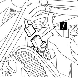
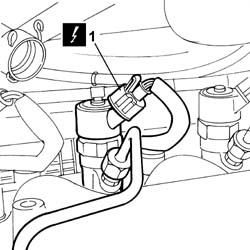
Carry out the same operation on all the injectors
1. Disconnect the electrical connection for the injector.
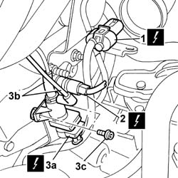
1. Disconnect the electrical connection for the heater plug wiring.
2. Disconnect the electrical connection for the engine coolant temperature sensor.
3. Disconnect the electrical connection (3a), disconnect the vacuum pipe (3b) and unscrew the bolts (3c), remove the intake manifold actuator control solenoid.
1. Disonnect the vacuum pipe.
2. Undo the bolts (2a) and remove the throttle body (2b).
1. Open the securing band (1a) using special pliers and the destructive band (1b).
2. Remove the oil vapour pipe.
| Description | Code | Function | |
|---|---|---|---|
| Caliper | Open the retaining bands |
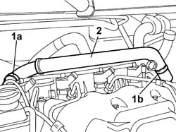
Op. 1080C54 EXHAUST GAS SUPPLY PIPE FROM E.G.R. VALVE TO INTAKE MANIFOLD - R.R.
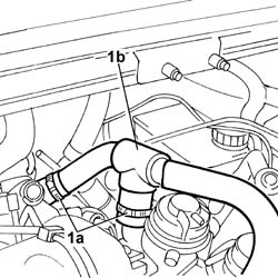
1. Open the bands (1a), disconnect the oil vapour pipe (1b) and move it out of the working area.
Position a suitable container for collecting the coolant.
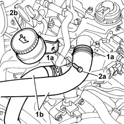
1. Open the bands (1a) using special pliers, move the coolant hoses (1b) out of the working area and collect the coolant.
2. Undo the bolt (2a) ande move the engine oil dipstick (2b) aside.
| Description | Code | Function | |
|---|---|---|---|
| Caliper | Open the retaining bands |
1. Open the securing band (1a) using the special pliers and move the pipe (1b) aside.
2. Remove the clip (2a) and disconnect the pipe (2b) from the thermostat.
| Description | Code | Function | |
|---|---|---|---|
| Caliper | Open the retaining bands |
1. Undo the fixing bolts (1a), release the head (1b) and remove the Swirl valve (1c).
2. Undo the nuts (2a), remove the mounting bracket (2b) and release it from the clips.
3. Undo the fixing bolt (3a) and remove the fitting (3b).
1. Undo the bolt and the nuts (1a) and remove the vacuum unit (1b).
1. Unscrew the bolts (1a) securing the delivery pipe to the water pump and remove the pipe protection (1b).
1. Open the securing band (1a) using the special pliers and disconnect the coolant pipe (1b).
| Description | Code | Function | |
|---|---|---|---|
| Caliper | Open the retaining bands |
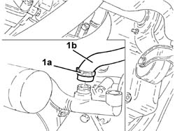
1. Open the securing band (1a) using the special pliers and remove the connector connecting the coolant pipes to the water pump (1b).
| Description | Code | Function | |
|---|---|---|---|
| Caliper | Open the retaining bands |
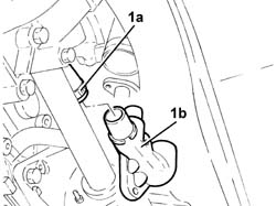
1. Disconnect the gear selector flexible cable (1a), undo the bolts (1b) and remove the bracket (1c) complete with counter-weight (1d).
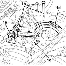
1. Undo the connector (1a) and disconnect the oil delivery pipe to the turbocharger from the engine block.
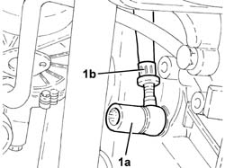
1. Disconnect the pipe (1a), undo the fixing bolts (1b) and remove the thermostat (1c) complete with pipes (1d).
1. Undo the quick-release fittings and disconnect the fuel pipes
2. Disconnect the electrical connection.
3. Undo the bolt (3a) securing the wiring channel and move out of the working area. Unscrew the bolts (3b) securing the fuel filter.
4. Remove the fuel filter assembly.
1. Undo the bolts (1a) and remove the fuel filter mounting (1b).
1. Disconnect the quick-release connectors for the fuel pipes.
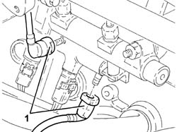
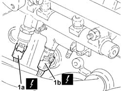
1. Disconnect the electrical connection for the fuel pressure sensor (1a) and the electrical connection for the fuel temperature sensor (1b).
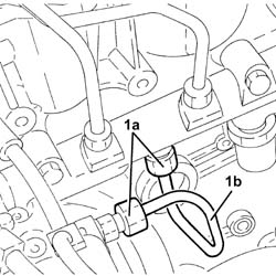
1. Undo the connectors (1a) and remove the rigid fuel supply pipe for the single rigid fuel delivery pipe (1b).
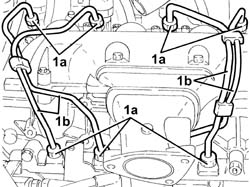
1. Undo the connectors (1a) and disconnect the rigid supply pipes from the single fuel supply pipe to the injectors (1b).
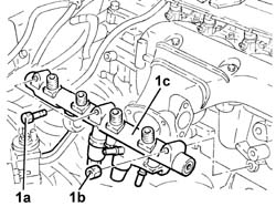
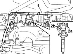
1. Undo the bolts (1a) and the nut (1b) and remove the single fuel manifold pipe complete with sensors (1c).
1. Disconnect the fuel return pipe from the injectors and move outside the working area.
2. Undo the fixing bolts (2a) and remove the injector (2b) using the appropriate tool.
Carry out the same operation on all the injectors
| Description | Code | Function | |
|---|---|---|---|
| Extractor | Injector extractor |
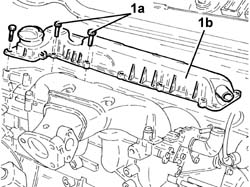
1. Undo bolts (1a) and remove the oil cover/separator (1b).
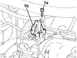
1. Undo the fixing bolts (1a) and remove the camshaft drive chain pretensioner (1b).
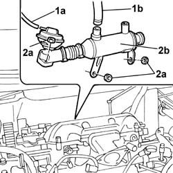
1. Disconnect the pipe (1a) from the EGR valve and the pipe (1b) from the EGR valve heat exchanger.
2. Undo the fixing nuts (2a) and remove the EGR valve - heat exchanger assembly (2b).
1. Remove the heat shield protection for the steering box.
1. Loosen the bolts (1a) securing the toothed driven pulley and flange (1b) using tool (1c) for counter-torque.
| Description | Code | Function | |
|---|---|---|---|
| 1c | Counter-torque | Counter-torque for exhaust side camshaft toothed driven pulley |
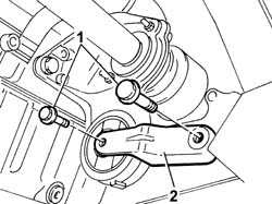
1. Undo the bolts fixing the reaction rod to the intermediate driveshaft support and to the suspension frame.
2. Remove the power unit lower reaction rod.
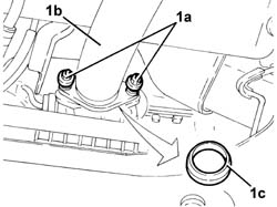
1. Undo the bolts (1a) and move the exhaust pipe (1b) away from the flange and keep the gasket (1c).
1. Undo the fixing bolts (1a) and remove the turbocharger exhaust flange (1b).
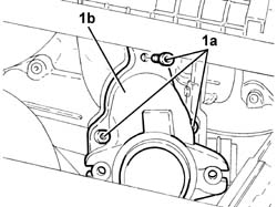
1. Undo the fixing bolts (1a) and move the oil outlet pipe from the turbocharger (1b) out of the way.
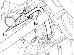
1. Undo the bolt (1a) and the retaining bolts (1b) and remove turbocharger mounting (1c).
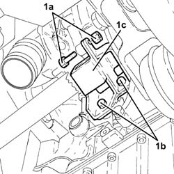
1. Undo the exhaust manifold nuts (1b), keep the spacers (1b) and release the manifold from the studs.
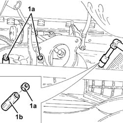
1. Undo the bolts (1a) and the studs (1b) and remove the single camshaft housing (1c).
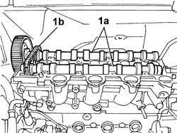
1. Remove the camshafts (1a) complete with chain (1b).
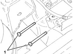
1. Undo the side bolts securing the engine support to the cylinder head.
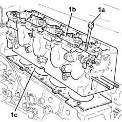
1. Undo the fixing bolts (1a) and remove the cylinder head (1b) and gasket (1c).
Refitting
For ground cylinder heads, it is necessary to correct any excess valve height. This operation requires the fitting of special undersize valves available as spares.
The nominal cylinder head height is 133 ± 0.05 mm; the maximum repair height is 132.6 ± 0.05 mm.
The flatness tolerance must be within 0.05 mm.
1. Measure the piston projection (1a) from the cylinder head gasket support plane using a dial guage and the tool (1b) following the instructions given below:
- place the piston in question at T.D.C.;
- bring the pointer in contact with the control point, shown in the diagram and zero the dial gauge;
- move the pointer on the engine block plane and take a reading for S1;
- bring the pointer in contact with the control point on the opposite side, shown in the diagram and zero the dial gauge;
- move the pointer on the engine block plane and take a reading for S2;
The piston projection in question is equal to the average value for the two readings
S = (S1 + S2) / 2
Repeat the above procedure for the remaining three pistons and check that the maximum difference between the projections is less than 0.07 mm.
1. Measure piston projection (1a) in two places 180° apart on the gudgeon pin centre line using the tool (1b) and take the average of the two values measured for each piston.
| Supporto comparatore | 1.870.404.000 | Sporgenza dal piano di appoggio testa cilindri | T.T |
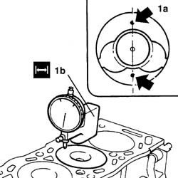
1. Select the correct size cylinder head gasket depending on the maximum average projections for each individual piston.
the difference between the minimum and maximum values should not be more than 0.07 mm.
Select a new cylinder head gasket on the basis of the specified values.
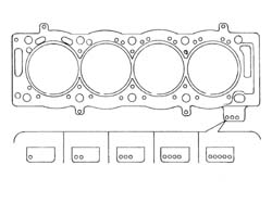
The references indicate the oversize levels.
Keep the gasket sealed in its nylon bag and do not remove from its protection until ready to fit.
Do not lubricate the gasket or contaminate with oil or grease.
| Piston projection (mm) |
| 0.55 ÷ 0.60 |
| number of references 1 |
| Piston projection (mm) |
| 0.61 ÷ 0.65 |
| number of references 2 |
| Piston projection (mm) |
| 0.66 ÷ 0.70 |
| number of references 3 |
| Piston projection (mm) |
| 0.71 ÷ 0.75 |
| number of references 4 |
1. Refit the cylinder head gasket (1a) in its seat and centre it on the locating pins (1b).
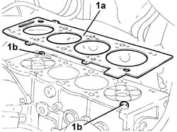
Position the cylinder head on the cylinder block/crankcase.
It is essential to check the length of the retaining bolts. The nominal length is 131.5 mm; the maximum permitted length is 134 mm. If it is greater, replace the bolts.
1. Tighten the bolts securing the cylinder head to the cylinder block to the recommended torque following the order illustrated and using the angular tightening tool.
| Value daNm | Fastening | Component | dia | |
|---|---|---|---|---|
| 2 | Pretightening, Bolt | CYLINDER HEAD |
| Value daNm | Fastening | Component | dia | |
|---|---|---|---|---|
| 6 | Tightening, Bolt | CYLINDER HEAD |
| Value daNm | Fastening | Component | dia | |
|---|---|---|---|---|
| 360° | Slackening the bolts (1 to 10) | CYLINDER HEAD |
| Description | Code | Function | |
|---|---|---|---|
| Torque wrench | Cylinder head bolts angular tightening |
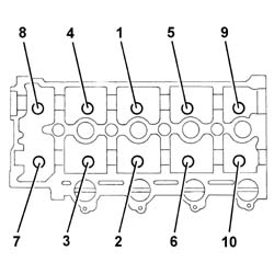
1. Position the camshafts (1a) complete with chain (1b).
2. Use an 8 mm calibrated pin (2a) to adjust the exhaust side camshaft timing and turn the notch (2b) upward to adjust the inlet side camshaft timing.
Apply silicone sealant to the mating surface between the single camshaft housing and the cylinder head.
1. Fit the single camshaft housing and tighten the bolts to the specified torque in the tightening order shown.
references 1 to 8 indicate the studs and references 9 to 36 indicate the bolts.
| Value daNm | Fastening | Component | dia | |
|---|---|---|---|---|
1 1 a8 | Stud | CAMSHAFT HOUSING |
| Value daNm | Fastening | Component | dia | |
|---|---|---|---|---|
0.5 9 to 36 | Tightening, Bolt | CAMSHAFT HOUSING |
| Value daNm | Fastening | Component | dia | |
|---|---|---|---|---|
1 9 to 36 | Pretightening, Bolt | CAMSHAFT HOUSING |
Tighten the side bolts securing the engine support to the cylinder head and tighten to the specified torque.
| da Nm | Fastening | Component | dia |
|---|---|---|---|
| 2.0 | Bolt with shoulder | ENGINE SUPPORT |
| da Nm | Fastening | Component | dia |
|---|---|---|---|
| 4.5 | Bolt | ENGINE SUPPORT |
Fit the exhaust manifold in position with the spacers and tighten the lower fixing nuts checking the torque.
Fit the turbocharger in place and tighten the fastenings.
| da Nm | Fastening | Component | dia |
|---|---|---|---|
| 2.5 | Nut | TURBOCHARGER FASTENING |
Fit the oil outlet pipe from the turbocharger and tighten the fixing bolts.
| da Nm | Fastening | Component | dia |
|---|---|---|---|
| 1.2 | Nut | TURBOCHARGER FASTENING |
Position the exhaust pipe on the flange after fitting the metal gasket, screw in the bolts and tighten to torque.
| da Nm | Fastening | Component | dia |
|---|---|---|---|
| 4.5 ± 0.7 | Nut | EXHAUST PIPE |
Fit the lower reaction link, screw in the bolts and tighten to torque.
| da Nm | Fastening | Component | dia |
|---|---|---|---|
| 6 | Nut | REACTION ROD |
Position the heat shield protection on the steering box.
Fit the EGR valve - heat exchanger assembly in its seat, tighten the nuts to the recommended torque and then connect the pipes to the inlets/outlets on the assembly.
| da Nm | Fastening | Component | dia |
|---|---|---|---|
| 3.0 | Nut | EGR VALVE ASSEMBLY |
Position the camshaft drive chain tensioner and tighten the bolts.
1. Position the oil vapour cover/separator in its seat and screw in the bolts. Tighten to the required torque and follow the tightening order indicated.
Remove the 8 mm calibrated pin.
Unscrew and remove the exhaust end camshaft flange using a tool for counter-torque.
| Description | Code | Function | |
|---|---|---|---|
| Counter-torque | Counter-torque |
Remove the exhaust camshaft oil seal. This operation is destructive for the oil seal, but take care not to damage the oil seal seat.
1. Fit a new exhaust end camshaft oil seal (1a) using the fitting tool (1b).
| Description | Code | Function | |
|---|---|---|---|
| 1b | Fitting tool | Fit the oil seal on the camshaft |
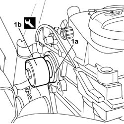
1. Fit the flange (1a) into its seat on the exhaust end camshaft and tighten the bolt (1b). Tighten to the specified torque using the tool (1c) for counter-torque.
| Description | Code | Function | |
|---|---|---|---|
| 1c | Counter-torque | Counter-torque |
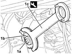
1. Fit the toothed driven pulley (1a) into its proper seat on the exhaust end camshaft and tighten the bolts (1b). Tighten to the specified torque using the tool (1c) for counter-torque.
| Description | Code | Function | |
|---|---|---|---|
| 1c | Counter-torque | Counter-torque for exhaust side camshaft toothed driven pulley |
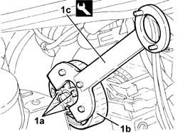
Fit the injectors in place and tighten the fixing nut checking the torque.
Connect the fuel return pipe to the injectors.
Position the single fuel manifold pipe complete with sensors and tighten the fixing nuts.
Fit the new rigid fuel supply pipe from the pressure pump to the single fuel manifold pipe and tighten the connectors to the specified torque.
- Carry out a pre-tightening cycle
| da Nm | Fastening | Component | dia |
|---|---|---|---|
| 0.8 | Pump side connector | PIPE FROM PRESSURE PUMP TO FUEL MANIFOLD |
| da Nm | Fastening | Component | dia |
|---|---|---|---|
| 2.4 | Manifold side connector | PIPE FROM PRESSURE PUMP TO FUEL MANIFOLD |
| da Nm | Fastening | Component | dia |
|---|---|---|---|
| 2.6 | Pump side connector | PIPE FROM PRESSURE PUMP TO FUEL MANIFOLD |
| da Nm | Fastening | Component | dia |
|---|---|---|---|
| 2.6 | Connector side connector | PIPE FROM PRESSURE PUMP TO FUEL MANIFOLD |
Each time work is carried out on the pipe from the pressure pump to the fuel manifold it must be replaced with a new one to prevent fuel leaks from the connectors.
Fit the new rigid fuel supply pipes from the single fuel manifold pipe to the individual injectors in place and tighten the bands to the recommended torque.
Connect the fuel pressure sensor electrical sensor and the fuel temperature sensor electrical connection located on the single fuel manifold pipe.
Connect the fuel pipe quick-release fittings to the single fuel manifold pipe.
Place the fuel filter mounting in position and tighten the fixing bolts.
Place the fuel filter on the mounting and tighten the fixing bolts.
Connect the fuel pipe rapid connectors to the filter.
Connect the electrical connection for the fuel filter sensor.
Fit the thermostat unit in place and tighten the fixing bolt checking the torque.
| da Nm | Fastening | Component | dia |
|---|---|---|---|
| 1.0 | Bolt pre-tightening | THERMOSTAT UNIT - R.R. |
| da Nm | Fastening | Component | dia |
|---|---|---|---|
| 1.0 | Nut Pre-tightening | THERMOSTAT UNIT - R.R. |
| da Nm | Fastening | Component | dia |
|---|---|---|---|
| 2.5 | Bolt pre-tightening | THERMOSTAT UNIT - R.R. |
| da Nm | Fastening | Component | dia |
|---|---|---|---|
| 2.5 | Nut Pre-tightening | THERMOSTAT UNIT - R.R. |
Connect the pipes to the thermostat and renew the securing bands.
Tighten the connector and connect the oil delivery pipe to the turbocharger to the engine block.
| da Nm | Fastening | Component | dia |
|---|---|---|---|
| 4.5 | Connector | OIL SUPPLY PIPE |
Fit the gear selection and engagement bracket in its seat together with the counterweight and tighten the bolts.
Connect the gear selection cable to the bracket.
Position the coolant pipe connector to the water pump complete with a new gasket and connect the hoses.
Tighten the bolts fixing the connector to the crankcase to torque.
| da Nm | Fastening | Component | dia |
|---|---|---|---|
| 2.0 | Bolt | PIPE CONNECTING CONNECTOR |
Renew the bands securing the hoses using the special tool.
| Description | Code | Function | |
|---|---|---|---|
| Caliper | Open the retaining bands |
Fit the protection for the water delivery pipe to the water pump.
Fit the vacuum pump and tighten the nuts and bolts.
| da Nm | Fastening | Component | dia |
|---|---|---|---|
| 2.0 | Bolt | VACUUM UNIT |
| da Nm | Fastening | Component | dia |
|---|---|---|---|
| 2.0 | Nut | VACUUM UNIT |
Position the oil vapour recovery fitting and tighten the bolt.
Fit the Swirl valve.
Tighten the bolts and secure the ball joint in its seat.
Fit the water/oil heat exchanger pipes to the thermostat and restore the fastenings.
Fit both coolant hoses on the thermostat and renew the fastening bands.
| Description | Code | Function | |
|---|---|---|---|
| Caliper | Open the retaining bands |
Fit the oil filler pipe and tighten the bolt.
Fit the oil vapour pipes and renew the retaining bands.
| Description | Code | Function | |
|---|---|---|---|
| Caliper | Open the retaining bands |
Op. 1080C54 EXHAUST GAS SUPPLY PIPE FROM E.G.R. VALVE TO INTAKE MANIFOLD - R.R.
Fit the throttle casing in position using the fixing bolts and connect the vacuum pipe to the valve on the throttle casing.
Connect the electrical connection for the heater plug wiring.
Connect the electrical connection for the engine coolant level sensor.
Fit the intake manifold actuator control solenoid and tighten the bolts.
Connect the vacuum pipes to the intake manifold actuator solenoid.
Connect the electrical connections for the injectors.
Connect the electrical connection for the cam angle sensor.
Op. 1048A50 TURBOCHARGER AIR INTAKE PIPE - R.R.
Op. 1048B22 AIR DELIVERY HOSE FROM HEAT EXCHANGER TO INTAKE MANIFOLD - R + R
Op. 1048A10 AIR FILTER ASSEMBLY - R.R.
Op. 1032B10 TOOTHED TIMING BELT - R + R FOR TIMING ADJUSTMENT OR REPLACEMENT
Op. 1008A46 POWER UNIT RIGID SUPPORT - TIMING SIDE - R.R.
Op. 1032D12 TIMING SYSTEM PROTECTIVE COVER(S) - R + R
Op. 1092A10 CRANKSHAFT PULLEY - R + R
Op. 1024B54 ENGINE FLYWHEEL PROTECTION - R.R
Op. 1092G10 SINGLE ENGINE BELT - R.R
Op. 1008C10 POWER UNIT UPPER SUPPORT - R R
Op. 5050B38 WINDSCREEN WIPER ASSEMBLY - R+R OR REPAIR
Op. 7055A18 L/H OR R/H SIDE RUBBING STRIP (ONE) FOR FRONT DOOR - R+R
Op. 5050B34 WINDSCREEN WIPER ARM/S COMPLETE WITH BLADE - R+R
[both]
Op. 5010B18 CLIMATE CONTROL UNIT AIR INTAKE - R.R.
[both]
Op. 5530B56 BATTERY DRIP TRAY COVER - R.R.
Op. 1048B10 RIGID SUPPLY PIPE (ONE) BETWEEN TURBOCHARGER AND HEAT EXCHANGER -R.R.
Op. 7055B54 UNDER ENGINE PROTECTION/GUARD - R.R.
Op. 7055B91 RIGHT FRONT WHEEL ARCH LINER - R.R.
Op. 4450B04 RIGHT FRONT WHEEL - R.R
Check engine fluid levels and top up where necessary.
Parts & tools for this job Staging For 2002 Fiat Ulysse
- PARTEngine gasket setSearch: Fiat Ulysse 2002 engine gasket set
- TOOLTorque wrenchSearch: 3/8 inch torque wrench
- TOOLFeeler gauge setSearch: feeler gauge set
Links open Amazon search results in a new tab. As an Amazon Associate I earn from qualifying purchases.