
Front ornament - r r
- Make
- Fiat
- Model
- Ulysse Factory Service Manual
- Year
- 2002–2010
- Section
- Mouldings on protections › Front ornament - r r
FRONT ORNAMENT - R R
Removing
- Open the bonnet.
1. Undo the bolts fixing the radiator grille to the bonnet lid.
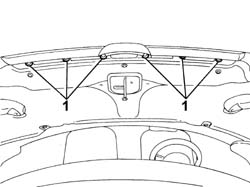
1. Remove the radiator grille.
2. At the bench, undo the bolt fixing the badge to the radiator grille.
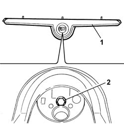
1. Remove the front badge.
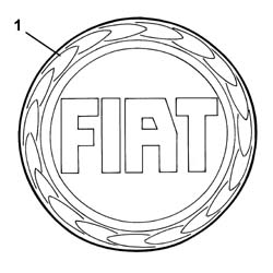
Refitting
- Position the front badge.
- Tighten the bolt fixing the badge to the radiator grille.
- Fit the radiator grille to the bonnet lid.
- Tighten the bolts fixing the radiator grille to the bonnet lid.
- Close the bonnet.
Removing
Position the vehicle on a lift.
Disconnect the negative battery terminal.
| Description | Connector | |
|---|---|---|
| Battery | A001 |
Op. 4450B04 RIGHT FRONT WHEEL R R
Op. 7055B54 UNDER-ENGINE GUARD - R R
Op. 7055B91 RIGHT FRONT WHEEL ARCH LINER - R.R.
Op. 5010B18 CLIMATE CONTROL UNIT AIR INTAKE - R.R.
Op. 5050B34 WINDSCREEN WIPER ARM/S COMPLETE WITH BLADE - R+R
Op. 7210E22 WINDSCREEN BASE TRIM
Op. 1088B10 ENGINE COOLING TANK - R + R
Op. 4130B10 POWER STEERING FLUID RESEVOIR R R
Op. 4130B12 POWER STEERING FLUID RESERVOIR MOUNTING/BRACKETS - POSITION
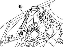
1. Remove the screen washer fluid filler (1a) complete with bracket (1b).
Op. 1016A42 LEFT HAND CYLINDER HEAD IGNITION COIL COVER - R+R
Op. 1008C10 POWER UNIT UPPER REACTION LINK R R.
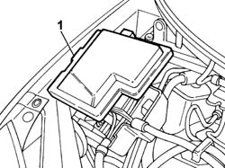
1. Remove the junction unit cover.
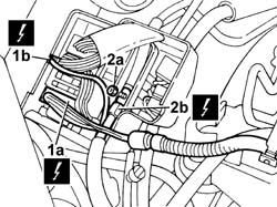
1. Disconnect the electrical connections (1a) for the engine wiring and the two-way connector (1b), then release the wiring and move it aside.
2. Undo the fixing nut (2a), disconnect the end of the cable (2b) and move the wiring aside.
| Description | Connector | |
|---|---|---|
| 1a | Engine compartment junction unit | B001 |
| Description | Connector | |
|---|---|---|
| 1b | Engine compartment junction unit | B001 |
| Description | Connector | |
|---|---|---|
| 2b | Engine compartment junction unit | B001 |
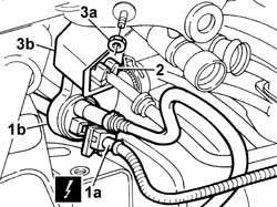
1. Disconnect the electrical connection and release the fuel vapour cut out valve (1b) from the mounting bracket.
2. Release the fuel supply pipe from the securing clip.
3. Undo the fixing nut (3a) and remove the mounting bracket (3b).
| Description | Connector | |
|---|---|---|
| 1a | Fuel vapour recovery solenoid valve | L010 |
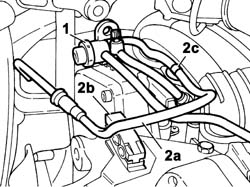
1. Release the fuel pressure regulator from the mounting located on the timing belt cover.
2. Release the fuel supply pipe (2a) from the retaining bracket (2b) and from the clip on the intake chamber (2c).
Op. 4410D16 BRACKET (ONE) RETAINING CHASSIS TO BODY - R R
Op. 1092G10 SINGLE ENGINE BELT R R
Op. 1092A10 CRANKSHAFT SERVICES PULLEY - R.R.
Op. 1092G15 ENGINE COMPONENT SINGLE BELT MOBILE TEMPERATURE - R RWITH BELT REMOVED
Op. 1092G21 ENGINE COMPONENT SINGLE BELT FIXED TENSIONER - R RWITH BELT REMOVED
1. Undo the bolt (1a) and release the timing side mounting for the engine coolant pipe (1b).
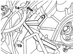
1. Undo the bolt and release the timing side side mounting for the engine coolant pipe.
2. Undo the bolt and release the flywheel side side mounting for the engine coolant pipe.
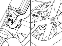
Op. 1032D12 TIMING SYSTEM PROTECTIVE COVER(S) - R + R
Op. 1008A46 CAM SHAFT LEFT RIGID MOUNT - R R
Op. 1008B10 POWER UNIT FRONT MOUNT (TIMING SIDE) FLEXIBLE BLOCK - REPLACE
Op. 1092C14 POWER STEERING PUMP/SELF LEVELLING SUSPENSION PUMP PULLEY - R + R WITH BELT REMOVED
1. Undo the bolts (1a) fixing the power assisted steering pump to the support, the bolts (1b) fixing the power assisted steering pump support to the engine (1c) and remove it from the engine.
2. Move the power assisted steering pump aside without disconnecting the pipes.
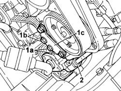
Adjust the toothed driving pulley to move the camshaft drive pulleys to the timing adjustment position (align the slots on the camshaft driven pulleys and the hole on the toothed drive pulley with the holes on the engine and cylinder heads)
1. Tighten the following in order: camshaft drive pulleys and then the toothed drive pulley, inserting the anchorage pins in the appropriate seats.
| Description | Code | Function | |
|---|---|---|---|
| 1 | Pins | 1.870.893.000 | Anchorage for toothed drive pulley and driven timing pulleys |
To facilitate camshaft alignment, loosen the toothed drive pulely bolts and turn the camshafts slightly with the aid of the pins that have been previously lubricated.
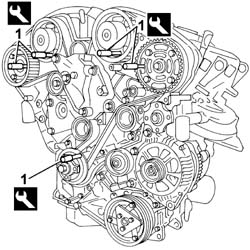
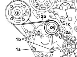
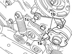
1. Undo the bolt (1a) fixing the timing belt moving tensioner, then loosen the bolts (1b) and the nut (1c) for the mobile tensioner.
2. Rotate the tensioner roller cam (2a) in a clockwise direction to loosen the tension and remove the timing belt (2b).
Refitting
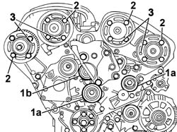
1. Check that the fixed tensioners (1a) and the water pump (1b) rotate freely and there is no clearance or stiffness.
2. Loosen the bolts fixing the camshaft pulleys.
3. Rotate the camshaft pulleys in a clockwise direction until they stop in contact with the pins.
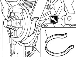
1. Attach the timing belt to the toothed drive pulley and secure it using the retainer (1).
| Description | Code | Function | |
|---|---|---|---|
| 1 | Caliper | 1.870.900.100 | Timing belt retaining pliers |
1. Position the timing belt on the fixed tensioner (1a), then make sure that the branch (1b) of the belt is taut.
2. Fit the timing belt on the left head exhaust valves camshaft pulley.
Slightly turn the camshaft pulley against the engine rotation direction to facilitate timing belt engagement.
The angular displacement of the pulley in relation to the timing belt must not exceed one tooth width.
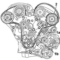
1. Fit the timing belt on the left head inlet valves camshaft pulley.
2. Fit the belt to the fixed tensioner.
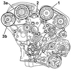
3. Fit the timing belt on the right head inlet valves drive pulley (3a) and on the right head exhaust valves drive pulley (3b).
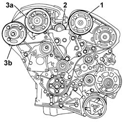
1. Fit the timing belt on the moving tensioner (1a), on the fixed tensioner (1c) and on the water pump pulley (1b).
2. Working through the reaction hole (2a) in the mobile tensioner support, fit the bolt (2b) and then tighten bolts (2b) and (2c) to the recommended torque.
| Value daNm | Fastening | Component | Ø | |
|---|---|---|---|---|
| 2b | 2.5 | Bolts | MOBILE TIMING TENSIONER |
| Value daNm | Fastening | Component | Ø | |
|---|---|---|---|---|
| 2c | 2.5 | Bolts | MOBILE TIMING TENSIONER |
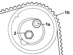
1. Working through reaction hole (1a), tension timing belt (1b) by turning the tensioner roller anticlockwise to the end of its travel.
Do not exceed the end travel point.
2. Tighten the nut on the timing belt mobile tensioner to the recommended torque.
| Value daNm | Fastening | Component | Ø | |
|---|---|---|---|---|
| 2 | 1 | Nut | MOVING TENSIONER |
It is ESSENTIAL to check, by unscrewing one bolt, that the timing belt driven pulleys are not at the end of their adjustment travel (with the slot in contact with the anchorage pins). If they are, repeat the toothed timing belt installation procedure.
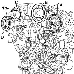
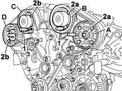
Respecting the order A, B, C, D:
1. Tighten the bolts (1a) fixing the camshaft driven pulleys on the left head and the bolts (1b) fixing the camshafts on the right head to the specified torque.
| Value daNm | Fastening | Component | Ø | |
|---|---|---|---|---|
| 1a | 1 | Bolts | LEFT HEAD DRIVEN PULLEYS |
| Value daNm | Fastening | Component | Ø | |
|---|---|---|---|---|
| 1b | 1 | Bolts | LEFT HEAD DRIVEN PULLEYS |
Remove the toothed drive pulley retaining clip
| Description | Code | Function | |
|---|---|---|---|
| 1 | Caliper | 1.870.900.100 | Timing belt retaining pliers |
Remove the timing belt pulley anchorage pins
| Description | Code | Function | |
|---|---|---|---|
| 1 | Pins | 1.870.893.000 | Anchorage for toothed drive pulley and driven timing pullies |
Turn the crankshaft in its normal direction of rotation.
Never try to rotate against the normal direction of rotation.
Position an anchorage pin only on the toothed drive pulley on the crankshaft
| Description | Code | Function | |
|---|---|---|---|
| 1 | Pins | 1.870.893.000 | Anchorage for toothed drive pulley and driven timing pulleys |
1. Loosen the nut retaining the timing belt mobile tensioner.
2. Align the tensioner roller references (2a) and (2b).
Tighten the mobile timing belt tensioner nut to torque without altering the roller position.
| Value daNm | Fastening | Component | Ø | |
|---|---|---|---|---|
| 1 | 3 | Nut | MOVING TENSIONER |
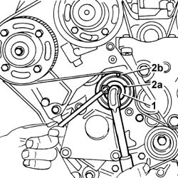
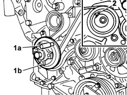
Remove the anchorage pin (1a) from the toothed drive pulley (1b).
| Description | Code | Function | |
|---|---|---|---|
| 1 | Pins | 1.870.893.000 | Anchorage for toothed drive pulley and driven timing pulleys |
Turn the crankshaft in its normal direction of rotation.
Never try to rotate against the normal direction of rotation.
Remove the anchorage pin (1a) from the toothed drive pulley (1b).
| Description | Code | Function | |
|---|---|---|---|
| 1 | Pins | 1.870.893.000 | Anchorage for toothed drive pulley and driven timing pulleys |
2. Check that the position of the timing belt mobile tensioner is correct.
If the reference marks on the timing belt tensioner roller are not aligned, repeat the operation.
Respecting the order A, B, C, D:
1. Fit the pins in the special housings in the driven pulleys.
| Description | Code | Function | |
|---|---|---|---|
| 1 | Pins | 1.870.893.000 | Mounting for toothed drive pulley and driven timing pulleys |
If the anchorage pins do not fit easily into their seats, loosen the bolts securing the pulleys to the crankshafts until this operation becomes possible.
It is ESSENTIAL to check, by unscrewing a bolt, that the driven timing pulleys are not at the end of their adjustment travel (with the slot in contact with the anchorage pins).
2. Tighten the bolts (2a) fixing the camshaft driven pulleys on the left head and the bolts (2b) fixing the camshafts on the right head.
| Value daNm | Fastening | Component | Ø | |
|---|---|---|---|---|
| 2a | 1 | Bolts | LEFT HEAD DRIVEN PULLEYS |
| Value daNm | Fastening | Component | Ø | |
|---|---|---|---|---|
| 2b | 1 | Bolts | LEFT HEAD DRIVEN PULLEYS |
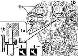
Remove the timing belt pulley anchorage pins
| Description | Code | Function | |
|---|---|---|---|
| 1 | Pins | 1.870.893.000 | Mounting for toothed drive pulley and driven timing pulleys |
Turn the crankshaft in its normal direction of rotation.
Never try to rotate against the normal direction of rotation.
1. Position a pin in the toothed drive pulley on the crankshaft, then position the remaining pins, checking that they can be inserted easily into the housings in the heads (1a) until they are in contact with the driven pulleys (1b).
If not, repeat the belt installation operation.
Remove the anchorage pins.
| Description | Code | Function | |
|---|---|---|---|
| 1 | Pins | 1.870.893.000 | Anchorage for toothed drive pulley and driven timing pulleys |
1. Position the power assisted steering pump complete with support (1a) on the engine, then tighten the fixing bolts (1b) and (1c) to the recommended torque.
| Value daNm | Fastening | Component | Ø | |
|---|---|---|---|---|
| 1b | 2.5 | Bolts | POWER ASSISTED STEERING PUMP R.R. WITH BELT REMOVED |
| Value daNm | Fastening | Component | Ø | |
|---|---|---|---|---|
| 1c | 4.0 | Bolts | POWER ASSISTED STEERING PUMP R.R. WITH BELT REMOVED |
Op. 1092C14 POWER STEERING PUMP/SELF LEVELLING SUSPENSION PUMP PULLEY - R + R WITH BELT REMOVED
Op. 1008B10 POWER UNIT FRONT MOUNT (TIMING SIDE) FLEXIBLE BLOCK - REPLACE
Op. 1008A46 CAM SHAFT LEFT RIGID MOUNT - R R
Op. 1032D12 TIMING SYSTEM PROTECTIVE COVER(S) - R + R
Undo the bolt and release the timing side side mounting for the engine coolant pipe.
Tighten the bolt and secure the right side mounting for the engine coolant pipe.
Tighten the bolt and secure the timing side side mounting for the engine coolant pipe.
Op. 1092A10 CRANKSHAFT SERVICES PULLEY - R.R.
Op. 1092G15 ENGINE COMPONENT SINGLE BELT MOBILE TEMPERATURE - R RWITH BELT REMOVED
Op. 1092G21 ENGINE COMPONENT SINGLE BELT FIXED TENSIONER - R RWITH BELT REMOVED
Op. 1092G10 SINGLE ENGINE BELT R R
Op. 4410D16 BRACKET (ONE) RETAINING CHASSIS TO BODY - R R
Position the fuel delivery pipe and secure the anchorages
Position the fuel pressure regulator in its seat.
Refit th fuel vapour cut-off valve mounting bracket.
Insert the fuel supply pipe into the anchorage clip.
Position the fuel vapour cut-off valve in its seat
Connect the electrical connection to the fuel vapour cut-off valve
| Description | Connector | |
|---|---|---|
| Fuel vapour recovery solenoid valve | L010 |
Reconnect the positive cable terminal for the starter motor and tighten the nut.
| Description | Connector | |
|---|---|---|
| Engine compartment junction unit | B001A |
Connect the electrical connection for the engine wiring.
| Description | Connector | |
|---|---|---|
| Engine compartment junction unit | B001B |
Connect the two-way electrical connection.
| Description | Connector | |
|---|---|---|
| Engine compartment junction unit | B001D |
Remove the junction unit cover.
Op. 1008C10 POWER UNIT UPPER REACTION LINK R R
Op. 1016A42 LEFT HAND CYLINDER HEAD IGNITION COIL COVER - R+R
Remove the screen washer fluid filler complete with bracket.
Op. 4130B12 POWER STEERING FLUID RESERVOIR MOUNTING/BRACKETS - POSITION
Op. 4130B10 POWER STEERING FLUID RESEVOIR R R
Op. 1088B10 ENGINE COOLING TANK - R + R
Op. 7210E22 WINDSCREEN BASE TRIM
Op. 5050B34 WINDSCREEN WIPER ARM/S COMPLETE WITH BLADE - R+R
Op. 5010B18 CLIMATE CONTROL UNIT AIR INTAKE - R.R.
Op. 7055B91 RIGHT FRONT WHEEL ARCH LINER - R.R.
Op. 7055B54 UNDER-ENGINE GUARD - R R
Op. 4450B04 RIGHT FRONT WHEEL R R
Disconnect the negative battery terminal.
| Description | Connector | |
|---|---|---|
| Battery | A001B |
Op. 0010T70 POWER ASSISTED STEERING FLUID - REPLACE
Op. 0010T21 COOLANT CHECK DENSITY AND TOP UP IF NECESSARY
Remove the vehicle from the lift.
Parts & tools for this job Staging For 2002 Fiat Ulysse
- TOOLTrim removal tool kitSearch: trim removal tool kit
- PARTTouch-up paintSearch: Fiat touch up paint
- PARTPanel clip assortmentSearch: Fiat panel clips assortment
Links open Amazon search results in a new tab. As an Amazon Associate I earn from qualifying purchases.