
Master cylinder (pump) - r + r
- Make
- Alfa Romeo
- Model
- GT Factory Service Manual
- Year
- 2003–2010
- Section
- Clutch release controls › Master cylinder (pump) - r + r
MASTER CYLINDER (PUMP) - R + R
Removing
Position the vehicle on a lift.
Proceed with the removal
Proceed with the removal
Op. 5530B52 BATTERY DRIP TRAY/SUPPORT - R.R..
Proceed with the removal
Op. 3340A12 ABS HYDRAULIC AND ELECTRONIC CONTROL UNIT.
Proceed with the removal
Op. 3340A13 ABS CENTRAL MOUNT - R R.
Proceed with the removal
Op. 4450B02 LEFT FRONT WHEEL R R.
Proceed with the removal
Op. 7055B65 ENGINGE BAY DUSTGUARD PROTECTION IN LEFT FRONT WHEEL ARCH R R.
Proceed with the removal
Op. 7055B90 LEFT FRONT WHEEL ARCH LINER - R.R..
Proceed with the removal
Op. 7055B54 UNDER-ENGINE GUARD - R R.
Proceed with the removal
Op. 3330D02 BRAKE SERVO/BRAKE PUMP ASSEMBLY - R R.
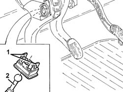
1. Working inside the passenger compartment, move the clutch pedal to the end of its travel, then undo the clips of the pedal lock device.
2. Release the master cylinder pushrod from the locking device.
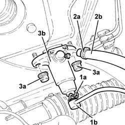
1. Remove split pin (1a) and disconnect the rigid delivery pipe from master cylinder (1b).
2. Loosen collar (2a) and disconnect the flexible pipe from the clutch reservoir to master cylinder (2b), master cylinder side.
3. Undo the nuts (3a) and remove the cylinder heads (3b).
Refitting
Place the master cylinder in its housing and secure it tightening the nuts to the recommended torque.
| Fastening | Component | Ø | Value (daNm) | |
|---|---|---|---|---|
| Nut | CLUTCH FLUID MASTER CYLINDER | M8 | 1.8 ÷ 2.6 |
Connect the flexible pipe from clutch cylinder to master cylinder, master cylinder side and secure with the collar.
Connect the rigid delivery pipe from the master cylinder, master cylinder side and secure with the split pin.
Connect the master cylinder pushrod to the locking device.
Connect the clutch pedal to the locking device by means of the clips.
Proceed with the refitting
Op. 3330D02 BRAKE SERVO/BRAKE PUMP ASSEMBLY - R R.
Proceed with the refitting
Op. 7055B54 UNDER-ENGINE GUARD - R R.
Proceed with the refitting
Op. 7055B90 LEFT FRONT WHEEL ARCH LINER - R.R..
Proceed with the refitting
Op. 7055B65 ENGINGE BAY DUSTGUARD PROTECTION IN LEFT FRONT WHEEL ARCH R R.
Proceed with the refitting
Op. 4450B02 LEFT FRONT WHEEL R R.
Proceed with the refitting
Op. 3340A13 ABS CENTRAL MOUNT - R R.
Proceed with the refitting
Op. 3340A12 ABS HYDRAULIC AND ELECTRONIC CONTROL UNIT.
Proceed with the refitting
Op. 0010T64 BRAKE AND OR CLUTCH FLUID CHECK LEVEL AND TOP UP AS NECESSARY.
Proceed with the refitting
Op. 0010T67 HYDRAULIC CLUTCH SYSTEM BLEED AIR.
Proceed with the refitting
Op. 0010T65 HYDRAULIC BRAKE SYSTEM BLEED AIR.
Proceed with the refitting
Op. 5530B52 BATTERY DRIP TRAY/SUPPORT - R.R..
Proceed with the refitting
Remove the vehicle from the lift.
Removing
Position the vehicle on a lift.
Proceed with the removal
Proceed with the removal
Op. 5530B52 BATTERY DRIP TRAY/SUPPORT - R.R..
Proceed with the removal
Op. 3340A12 ABS HYDRAULIC AND ELECTRONIC CONTROL UNIT.
Proceed with the removal
Op. 3340A13 ABS CENTRAL MOUNT - R R.
Proceed with the removal
Op. 4450B02 LEFT FRONT WHEEL R R.
Proceed with the removal
Op. 7055B65 ENGINGE BAY DUSTGUARD PROTECTION IN LEFT FRONT WHEEL ARCH R R.
Proceed with the removal
Op. 7055B90 LEFT FRONT WHEEL ARCH LINER - R.R..
Proceed with the removal
Op. 7055B54 UNDER-ENGINE GUARD - R R.
Proceed with the removal
Op. 3330D02 BRAKE SERVO/BRAKE PUMP ASSEMBLY - R R.
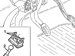
1. Working inside the passenger compartment, move the clutch pedal to the end of its travel, then undo the clips of the pedal lock device.
2. Release the master cylinder pushrod from the locking device.
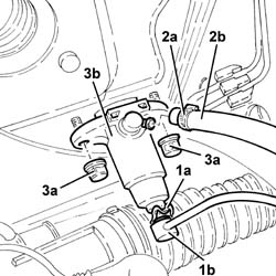
1. Remove split pin (1a) and disconnect the rigid delivery pipe from master cylinder (1b).
2. Loosen collar (2a) and disconnect the flexible pipe from the clutch reservoir to master cylinder (2b), master cylinder side.
3. Undo the nuts (3a) and remove the cylinder heads (3b).
Refitting
Place the master cylinder in its housing and secure it tightening the nuts to the recommended torque.
| Fastening | Component | Ø | Value (daNm) | |
|---|---|---|---|---|
| Nut | CLUTCH FLUID MASTER CYLINDER | M8 | 1.8 ÷ 2.6 |
Connect the flexible pipe from clutch cylinder to master cylinder, master cylinder side and secure with the collar.
Connect the rigid delivery pipe from the master cylinder, master cylinder side and secure with the split pin.
Connect the master cylinder pushrod to the locking device.
Connect the clutch pedal to the locking device by means of the clips.
Proceed with the refitting
Op. 3330D02 BRAKE SERVO/BRAKE PUMP ASSEMBLY - R R.
Proceed with the refitting
Op. 7055B54 UNDER-ENGINE GUARD - R R.
Proceed with the refitting
Op. 7055B90 LEFT FRONT WHEEL ARCH LINER - R.R..
Proceed with the refitting
Op. 7055B65 ENGINGE BAY DUSTGUARD PROTECTION IN LEFT FRONT WHEEL ARCH R R.
Proceed with the refitting
Op. 4450B02 LEFT FRONT WHEEL R R.
Proceed with the refitting
Op. 3340A13 ABS CENTRAL MOUNT - R R.
Proceed with the refitting
Op. 3340A12 ABS HYDRAULIC AND ELECTRONIC CONTROL UNIT.
Proceed with the refitting
Op. 0010T64 BRAKE AND OR CLUTCH FLUID CHECK LEVEL AND TOP UP AS NECESSARY.
Proceed with the refitting
Op. 0010T67 HYDRAULIC CLUTCH SYSTEM BLEED AIR.
Proceed with the refitting
Op. 0010T65 HYDRAULIC BRAKE SYSTEM BLEED AIR.
Proceed with the refitting
Op. 5530B52 BATTERY DRIP TRAY/SUPPORT - R.R..
Proceed with the refitting
Remove the vehicle from the lift.
Removing
- Position the vehicle on a lift.
- Op. 5530B10 BATTERY - R+R
- Op. 5530B52 BATTERY DRIP TRAY/SUPPORT - R.R.
- Op. 3340A12 ABS HYDRAULIC AND ELECTRONIC CONTROL UNIT
- Op. 3340A13 ABS CENTRAL MOUNT - R R
- Op. 3330D02 BRAKE SERVO/BRAKE PUMP ASSEMBLY - R R
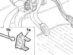
- Remove the clip (1a) and release master cylinder pushrod (1b) from the clutch pedal.
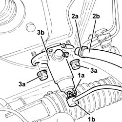
- Remove split pin (1a) and disconnect the rigid delivery pipe from master cylinder (1b).
- Loosen collar (2a) and disconnect the flexible pipe from the clutch reservoir to master cylinder (2b), master cylinder side.
- Undo the nuts (3a) and remove the cylinder heads (3b).
Refitting
- Place the master cylinder in its housing and secure it tightening the nuts to the recommended torque.
| Fastening | Component | Ø | Value (daNm) | |
|---|---|---|---|---|
| Nut | Clutch master cylinder (pump) | M8 | 1.8 - 2.4 daNm |
- Connect the flexible pipe from clutch cylinder to master cylinder, master cylinder side and secure with the collar.
- Connect the rigid delivery pipe from the master cylinder, master cylinder side and secure with the split pin.
- Connect the master cylinder pushrod to the clutch pedal and secure with a clip.
- Op. 3330D02 BRAKE SERVO/BRAKE PUMP ASSEMBLY - R R
- Op. 3340A13 ABS CENTRAL MOUNT - R R
- Op. 3340A12 ABS HYDRAULIC AND ELECTRONIC CONTROL UNIT
- Op. 0010T67 HYDRAULIC CLUTCH SYSTEM BLEED AIR
- Op. 5530B52 BATTERY DRIP TRAY/SUPPORT - R.R.
- Op. 5530B10 BATTERY - R+R
- Op. 0010T65 HYDRAULIC BRAKE SYSTEM BLEED AIR
- Remove the vehicle from the lift.
Parts & tools for this job Staging For 2003 Alfa Romeo GT
- TOOLBrake bleeder kitSearch: one man brake bleeder kit
- FLUIDBrake fluidSearch: brake fluid
- TOOLBrake line flaring toolSearch: brake line flaring tool
Links open Amazon search results in a new tab. As an Amazon Associate I earn from qualifying purchases.