
Abs hydraulic and electronic control unit
- Make
- Alfa Romeo
- Model
- GT Factory Service Manual
- Year
- 2003–2010
- Section
- Anti-lock brake system – ABS › Abs hydraulic and electronic control unit
ABS HYDRAULIC AND ELECTRONIC CONTROL UNIT
Removing
Position the vehicle on a lift.
Proceed with the removal
Proceed with the removal
Op. 5530B52 BATTERY DRIP TRAY/SUPPORT - R.R..
Proceed with the removal
Op. 4450B10 TYRE INFLATION VALVE CAP - REPLACE.
Remove the protective cap from the bleed valve on the brake caliper.
Connect the recovery device (pipe and reservoir) to the brake caliper bleed valve.
Operate the brake pedal until the brake/clutch reservoir is drained.
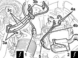
1. Disconnect the electrical connection from the brake fluid minimum level warning light switch.
| Description | Connector | |
|---|---|---|
| 1 | Brake fluid level sensor (switch) | See K25 BRAKE FLUID LEVEL SENSOR (SWITCH) ( FRONT ) |
2. Disconnect the electrical connection from the ABS hydraulic and electronic control unit.
| Description | Connector | |
|---|---|---|
| 2 | ABS control unit | See M50 ABS CONTROL UNIT ( FRONT ) |
3. Undo the connectors (3a) and (3b) and remove the rigid pipes from the master cylinder to the A.B.S. hydraulic control unit (3c).
4. Undo the connectors (4a) and disconnect the rigid pipes from the hydraulic control unit to the brake calipers (4b), hydraulic control unit side.
5. Release the A.B.S. pipes from the fastenings.
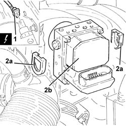
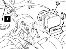
1. Disconnect the electrical connection from the VDC system pressure sensor.
| Description | Connector | |
|---|---|---|
| 1 | Pressure sensor (VDC) | See K72 PRESSURE SENSOR VDC ( FRONT ) |
2. Remove the clips (2a) and remove the ABS electronic and hydraulic control unit (2b).
Refitting
The letters indicating to which caliper and to which brake pump outlet they should be connected are stamped on the control unit at each outlet.
RR = to the right rear brake (pipe marked with light blue band)
LR = to the left rear brake (pipe marked with green band)
RF = to the right front caliper (pipe marked with yellow band)
LF = to the left front caliper (pipe marked with white band)
MC1 = from the main circuit pump/flange side (pipe marked with black band or pink band when the pipe polyammide resin is black)
MC2 = from the secondary circuit pump/front (pipe marked with brown band).
Place the A.B.S. hydraulic and electronic control unit in position and secure it using the clips.
Connect the electrical connection to the VDC system pressure sensor.
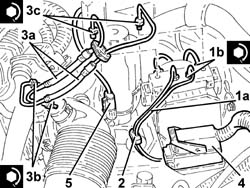
1. Connect the rigid pipes from the hydraulic control unit to the brake caliper (1a) hydraulic control unit side and tighten the connectors (1b) to the recommended torque.
| Fastening | Component | Ø | Value (daNm) | |
|---|---|---|---|---|
| 1b | Connector | PIPE FROM CONTROL UNIT TO FRONT BRAKES | M10/M12 | (Control unit side) 1.3 - 1.5 |
2. Secure the rigid pipes from the hydraulic control unit to the brake calipers to the fastenings.
3. Place the rigid pipes from the master cylinder to the A.B.S. hydraulic control unit (3a) in position and tighten the connectors (3b) and (3c) to the recommended torque.
| Fastening | Component | Ø | Value (daNm) | |
|---|---|---|---|---|
| 3b | Connector | PIPE FROM PUMP TO HYDRAULIC CONTROL UNIT | M12 | (Master cylinder side) 1.3 - 1.5 |
| Fastening | Component | Ø | Value (daNm) | |
|---|---|---|---|---|
| 3c | Connector | PIPE FROM PUMP TO HYDRAULIC CONTROL UNIT | M12 | (ABS control unit side) 1.3 - 1.5 |
4. Connect the electrical connection to the ABS hydraulic and electronic control unit.
5. Connect the electrical connection to the brake-clutch fluid minimum level warning light switch.
Proceed with the refitting
Op. 5530B52 BATTERY DRIP TRAY/SUPPORT - R.R..
Proceed with the refitting
Bleed the air from the hydraulic braking system
Op. 3330A14 FRONT OR REAR HYDRAULIC BRAKE SYSTEM - BLEED.
Proceed with the refitting
Op. 4450B10 TYRE INFLATION VALVE CAP - REPLACE.
Remove the vehicle from the lift.
Removing
Position the vehicle on a lift.
Proceed with the removal
Proceed with the removal
Op. 5530B52 BATTERY DRIP TRAY/SUPPORT - R.R..
Proceed with the removal
Op. 4450B02 LEFT FRONT WHEEL R R.
Proceed with the removal
Op. 3330C30 BRAKE FLUID RESERVOIR - R + R AND WASH INSIDE.
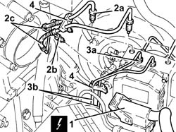
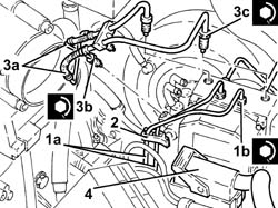
1. Disconnect the electrical connection from the ABS hydraulic and electronic control unit.
| Description | Connector | |
|---|---|---|
| 1 | ABS control unit | See M50 ABS CONTROL UNIT ( FRONT ) |
2. Undo the connectors (2a) and (2b) and remove the rigid pipes from the master cylinder to the A.B.S. hydraulic control unit (2c).
3. Undo the connectors (3a) and disconnect the rigid pipes from the hydraulic control unit to the brake calipers (3b), hydraulic control unit side.
4. Release the A.B.S. pipes from the fastenings.
1. Disconnect the electrical connection from the VDC system pressure sensor.
| Description | Connector | |
|---|---|---|
| 1 | Pressure sensor (VDC) | See K72 PRESSURE SENSOR VDC ( FRONT ) |
2. Remove the clips (2a) and remove the ABS electronic and hydraulic control unit (2b).
Refitting
The letters indicating to which caliper and to which brake pump outlet they should be connected are stamped on the control unit at each outlet.
RR = to the right rear brake (pipe marked with light blue band)
LR = to the left rear brake (pipe marked with green band)
RF = to the right front caliper (pipe marked with yellow band)
LF = to the left front caliper (pipe marked with white band)
MC1 = from the main circuit pump/flange side (pipe marked with black band or pink band when the pipe polyammide resin is black)
MC2 = from the secondary circuit pump/front (pipe marked with brown band).
Place the A.B.S. hydraulic and electronic control unit in position and secure it using the clips.
Connect the electrical connection to the VDC system pressure sensor.
1. Connect the rigid pipes from the hydraulic control unit to the brake caliper (1a) hydraulic control unit side and tighten the connectors (1b) to the recommended torque.
| Fastening | Component | Ø | Value (daNm) | |
|---|---|---|---|---|
| 1b | Connector | PIPE CENTRE RIGID BRAKING PIPE/REAR BRAKES | M10/M12 | (Control unit side) 1.4 - 1.8 |
2. Secure the rigid pipes from the hydraulic control unit to the brake calipers to the fastenings.
3. Place the rigid pipes from the master cylinder to the A.B.S. hydraulic control unit (3a) in position and tighten the connectors (3b) and (3c) to the recommended torque.
| Fastening | Component | Ø | Value (daNm) | |
|---|---|---|---|---|
| 3b | Connector | PIPE FROM PUMP TO HYDRAULIC CONTROL UNIT | M12 | (Master cylinder side) 1.4 - 1.8 |
| Fastening | Component | Ø | Value (daNm) | |
|---|---|---|---|---|
| 3c | Connector | PIPE FROM PUMP TO HYDRAULIC CONTROL UNIT | M12 | (ABS control unit side) 1.4 - 1.8 |
4. Connect the electrical connection to the ABS hydraulic and electronic control unit.
Proceed with the refitting
Op. 3330C30 BRAKE FLUID RESERVOIR - R + R AND WASH INSIDE.
Proceed with the refitting
Op. 5530B52 BATTERY DRIP TRAY/SUPPORT - R.R..
Proceed with the refitting
Top up the brake-clutch fluid level
Op. 0010T64 BRAKE AND OR CLUTCH FLUID CHECK LEVEL AND TOP UP AS NECESSARY.
Bleed the air from the hydraulic braking system
Op. 0010T65 HYDRAULIC BRAKE SYSTEM BLEED AIR.
Proceed with the refitting
Op. 4450B02 LEFT FRONT WHEEL R R.
Remove the vehicle from the lift.
Removing
Position the vehicle on a lift.
Proceed with the removal
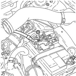
During the removal of the battery take care to also disconnect the starter motor supply lead, shown in the diagram, from the maxi fuse box.
Proceed with the removal
Op. 4450B02 LEFT FRONT WHEEL R R.
Remove the protective cap from the bleed valve on the brake caliper.
Connect the recovery device (pipe and reservoir) to the brake caliper bleed valve.
Operate the brake pedal until the brake/clutch reservoir is drained.
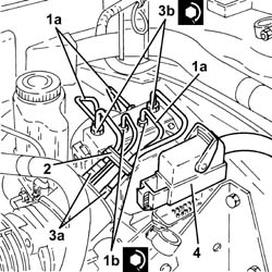
1. Disconnect the electrical connection from the ABS hydraulic and electronic control unit.
| Description | Connector | |
|---|---|---|
| 1 | ABS control unit | See M50 ABS CONTROL UNIT ( FRONT ) |
2. Undo the connectors (2a) and disconnect the rigid pipes from the master cylinder to the A.B.S.hydraulic control unit (2b), hydraulic control unit side.
3. Undo the connectors (3a) and disconnect the rigid pipes from the hydraulic control unit to the brake calipers (3b), hydraulic control unit side.
4. Release the A.B.S. pipes from the fastenings.
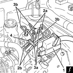
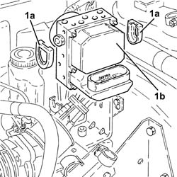
1. Remove the clips (1a) and remove the ABS electronic and hydraulic control unit (1b).
Refitting
The letters indicating to which caliper and to which brake pump outlet they should be connected are stamped on the control unit at each outlet.
RR = to the right rear brake (pipe marked with light blue band)
LR = to the left rear brake (pipe marked with green band)
RF = to the right front caliper (pipe marked with yellow band)
LF = to the left front caliper (pipe marked with white band)
MC1 = from the main circuit pump/flange side (pipe marked with black band or pink band when the pipe polyammide resin is black)
MC2 = from the secondary circuit pump/front (pipe marked with brown band).
Place the A.B.S. hydraulic and electronic control unit in position and secure it using the clips.
1. Connect the rigid pipes from the hydraulic control unit to the brake caliper (1a) hydraulic control unit side and tighten the connectors (1b) to the recommended torque.
| Fastening | Component | Ø | Value (daNm) | |
|---|---|---|---|---|
| 1b | Connector | PIPE CENTRE RIGID BRAKING PIPE/REAR BRAKES | M10/M12 | (ABS control unit side) 1.3 - 1.5 |
2. Secure the rigid pipes from the hydraulic control unit to the brake calipers to the fastenings.
3. Connect the rigid pipes from the master cylinder to the A.B.S. hydraulic control unit (3a), hydraulic control unit side and tighten the connectors (3b) to the recommended torque.
| Fastening | Component | Ø | Value (daNm) | |
|---|---|---|---|---|
| 3b | Connector | PIPE FROM PUMP TO HYDRAULIC CONTROL UNIT | M12 | (ABS control unit side) 1.3 - 1.5 |
4. Connect the electrical connection to the ABS hydraulic and electronic control unit.
Proceed with the refitting
Bleed the air from the hydraulic braking system
Op. 0010T65 HYDRAULIC BRAKE SYSTEM BLEED AIR.
Proceed with the refitting
Op. 4450B02 LEFT FRONT WHEEL R R.
Remove the vehicle from the lift.
Parts & tools for this job Staging For 2003 Alfa Romeo GT
- TOOLOBD2 scanner with ABSSearch: OBD2 scanner ABS SRS
- TOOLDigital multimeterSearch: automotive digital multimeter
Links open Amazon search results in a new tab. As an Amazon Associate I earn from qualifying purchases.