
Inlet manifold - r + r and replace seal
- Make
- Alfa Romeo
- Model
- 159 Factory Service Manual
- Year
- 2005–2011
- Section
- Inlet and exhaust manifolds › Inlet manifold - r + r and replace seal
INLET MANIFOLD - R + R AND REPLACE SEAL
Removing
- Position the vehicle on a lift.
Op. 1016A10 SOUND-PROOFING COVER - R.R
Op. 1048B22 AIR SUPPLY HOSE FROM HEAT EXCHANGER TO INTAKE MANIFOLD - R + R
Op. 1060G50 THROTTLE BODY - R.R
Op. 1080C24 E.G.R. SYSTEM SOLENOID - R + R
Op. 1048A50 TURBOCHARGER AIR INTAKE PIPE - R.R.
Op. 1084A16 OIL DIPSTICK PIPE - R.R
Op. 1048A28 VACUUM AIR CIRCUIT RESONATOR PIPE - R+R
Op. 4450B04 RIGHT FRONT WHEEL - R.R
Op. 7055B66 ENGINE COMPARTMENT DUST COVER IN RIGHT FRONT WHEEL ARCH - R.R.
Op. 7055B91 RIGHT FRONT WHEEL ARCH LINER - R.R.
Op. 4410D16 BRACKET (ONE) RETAINING CHASSIS TO BODY - R R
Op. 1092G10 SINGLE ENGINE BELT - R.R
Op. 1092A10 CRANKSHAFT PULLEY - R + R
Op. 1032B10 TOOTHED TIMING BELT - R + R FOR TIMING ADJUSTMENT OR REPLACEMENT
Op. 1060E30 PRESSURE PUMP DRIVE PULLEY - R.R.
Op. 1060E10 DIESEL INJECTION PRESSURE PUMP - R.R.
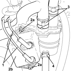
1. Disconnect the vacuum pipes from the vacuum reservoir.
2. Undo the nuts (2a) and remove the vacuum reservoir (2b).
3. Loosen the collars and disconnect the engine oil vapour recovery pipes, engine oil vapour separator side.
4. Loosen the band and disconnect the condensed engine oil recovery pipe, engine oil vapour separator side.
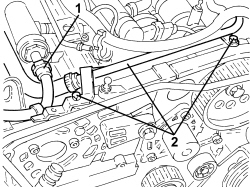
1. Disconnect the rapid connector for the fuel return pipe to the tank, fuel return manifold side.
2. Undo the bolts securing the rigid section of the engine oil vapour recovery pipe and move aside.
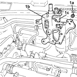
1. Undo the fastenings (1a) and remove the bracket (1b) complete with engine oil vapour separator (1c).
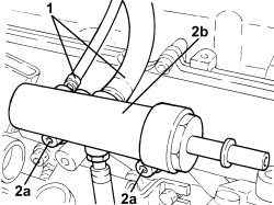
1. Loosen the collars and disconnect the fuel return pipes, fuel return manifold side.
2. Undo the bolts (2a) and remove the fuel pressure manifold (2b).
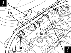
1. Loosen the collars, undo the bolts (1a) and move the coolant return pipe to the engine coolant reservoir (1b).
2. Disconnect the electrical connection for the pressure relief sensor.
| Description | Connector | |
|---|---|---|
| 2 | Supercharging sensor | See K082 SUPERCHARGING SENSOR |
3. Disconnect the electrical connections from the glow plugs and move the electrical wiring sideways.
| Description | Connector | |
|---|---|---|
| 3 | Heater plugs | See A040 HEATER PLUGS |
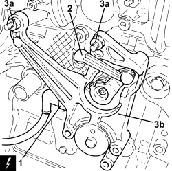
1. Disconnect the electrical connection from the intake duct throttle spindle control valve.
| Description | Connector | |
|---|---|---|
| 1 | Flow modifier solenoid valve | See L064 FLOW MODIFYING SOLENOID VALVE |
2. Disconnect the linkage of the intake duct throttle spindle control valve.
3. Unscrew nuts (3a) and remove the intake duct throttle spindle control valve (3b).
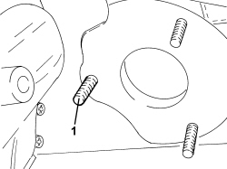
1. Remove the stud shown in the figure securing the pressure pump from the pressure pump mounting.
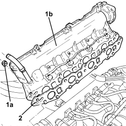
1. Undo the nuts (1a) and remove the intake manifold (1b).
2. Remove the intake manifold gasket.
Refitting
1. Place a new intake manifold gasket in position.
2. Place the intake manifold mounting (2a) in its housing and secure it by tightening the nuts (2b) to the recommended torque.
| Component | Fastening | dia | Value (daNm) | Validity |
|---|---|---|---|---|
| Intake manifold | Nut | M8 | (cylinder head side) 2.3 - 2.8 | 1.9 JTD 16V 2.4 JTD 20V |
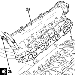
- Refit the pressure pump stud in its seat on the pressure pump mount.
1. Refit the intake duct throttle spindle (1a) in its seat and secure by tightening nuts (1b) to the specified torque.
| Component | Fastening | dia | Value (daNm) | Validity |
|---|---|---|---|---|
| Throttle carrier shaft control valve for inlet ducts | Nut | M | 1.9 JTD 16V 2.4 JTD 20V |
2. Connect the linkage of the intake duct throttle spindle control valve.
3. Connect the electrical connection to the intake duct throttle spindle control valve.
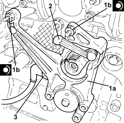
- Refit the electrical wiring and connect the engine wiring electrical connections to the glow plugs.
- Connect the electrical connection for the pressure relief sensor.
- Place the coolant return pipe to the engine coolant reservoir in position and tighten the bolts and collars.
- Place the fuel return manifold pipe in its housing and secure it using the bolts.
- Connect the fuel return pipes, fuel return manifold side, and tighten the collars.
- Refit the bracket with engine oil vapour separator and secure.
- Refit the rigid engine oil vapour recovery pipe section and secure with the bolts.
- Connect the rapid connector for the fuel return pipe to the tank, fuel return manifold side.
- Connect the condensate oil recovery pipe, engine oil vapour separator side, and tighten the band.
- Connect the engine oil vapour recovery pipes, engine oil vapour separator side, and tighten the collars.
- Refit the vacuum reservoir back in its housing and secure it using the nuts.
- Connect the vacuum pipes to the vacuum reservoir.
Op. 1060E10 DIESEL INJECTION PRESSURE PUMP - R.R.
Op. 1060E30 PRESSURE PUMP DRIVE PULLEY - R.R.
Op. 1032B10 TOOTHED TIMING BELT - R + R FOR TIMING ADJUSTMENT OR REPLACEMENT
Op. 1092A10 CRANKSHAFT PULLEY - R + R
Op. 1092G10 SINGLE ENGINE BELT - R.R
Op. 4410D16 BRACKET (ONE) RETAINING CHASSIS TO BODY - R R
Op. 7055B91 RIGHT FRONT WHEEL ARCH LINER - R.R.
Op. 7055B66 ENGINE COMPARTMENT DUST COVER IN RIGHT FRONT WHEEL ARCH - R.R.
Op. 4450B04 RIGHT FRONT WHEEL - R.R
Op. 1048A28 VACUUM AIR CIRCUIT RESONATOR PIPE - R+R
Op. 1084A16 OIL DIPSTICK PIPE - R.R
Op. 1048A50 TURBOCHARGER AIR INTAKE PIPE - R.R.
Op. 1080C24 E.G.R. SYSTEM SOLENOID - R + R
Op. 1060G50 THROTTLE BODY - R.R
Op. 1048B22 AIR SUPPLY HOSE FROM HEAT EXCHANGER TO INTAKE MANIFOLD - R + R
Op. 1016A10 SOUND-PROOFING COVER - R.R
- Remove the vehicle from the lift.
- On this car, it is not possible to remove/refit the intake manifold on the car.
To perform this operation, the power unit must be removed/refitted
Op. 1004B10 POWER UNIT WITH MANUAL GEARBOX - R.R
and then the operation must be carried out at the bench, customising the operation according to the engine service procedures.
Removing
- Position the vehicle on a lift.
- Make sure that the ignition key is in the OFF position, then disconnect the battery terminal (-).
Op. 4450B04 RIGHT FRONT WHEEL - R.R
Op. 7055B66 ENGINE COMPARTMENT DUST COVER IN RIGHT FRONT WHEEL ARCH - R.R.
Op. 7055B91 RIGHT FRONT WHEEL ARCH LINER - R.R.
Op. 1092G10 SINGLE ENGINE BELT - R.R
Op. 1092A10 CRANKSHAFT PULLEY - R + R
Op. 1016A10 SOUND-PROOFING COVER - R.R
Op. 1048A10 AIR FILTER ASSEMBLY - R.R.
Op. 7055B54 UNDER ENGINE PROTECTION/GUARD - R.R.
Op. 1008B10 POWER UNIT FRONT SUPPORT FLEXIBLE MOUNTING (TIMING SIDE) - REPLACE
Op. 1032D12 TIMING SYSTEM PROTECTIVE COVER(S) - R + R
Op. 1092G20 ENGINE COMPONENT SINGLE BELT FIXED TENSIONER - ONE - R + R
Op. 1008A46 POWER UNIT RIGID SUPPORT - TIMING SIDE - R.R.
Op. 1032B10 TOOTHED TIMING BELT - R + R FOR TIMING ADJUSTMENT OR REPLACEMENT
Op. 5530B52 BATTERY SUPPORT/DRIP TRAY - R.R
Op. 1048B27
Op. 1060G50 THROTTLE BODY - R.R
Op. 1080C24 E.G.R. SYSTEM SOLENOID - R + R
Op. 1060F36 PIPES (ALL) FROM FUEL MANIFOLD TO INJECTOR - R.R.
Op. 1060F20 PIPE FROM PRESSURE PUMP TO FUEL MANIFOLD - R.R.
Op. 1060F30 SINGLE FUEL MANIFOLD PIPE - R.R.
Op. 1048B22 AIR SUPPLY HOSE FROM HEAT EXCHANGER TO INTAKE MANIFOLD - R + R
Op. 1080C80 EXHAUST GAS/WATER HEAT EXCHANGER FOR EGR SYSTEM - R.R
Op. 1060F50 FUEL RETURN MANIFOLD - R.R.
Op. 1080D34 ENGINE OIL VAPOUR SEPARATOR - R + R
- Disconnect the electrical connections from the heater plugs and move the electrical wiring sideways.
| Description | Connector | |
|---|---|---|
| Heater plugs | See A040 HEATER PLUGS |
- Disconnect the electrical connection for the pressure relief sensor.
| Description | Connector | |
|---|---|---|
| Supercharging sensor | See K082 SUPERCHARGING SENSOR |
- Disconnect the electrical connection from the fuel pressure regulator on the pressure pump.
| Description | Connector | |
|---|---|---|
| Fuel pressure regulator | See N077 FUEL PRESSURE REGULATOR |
- Disconnect the fuel supply pipe rapid connector, pressure pump side.
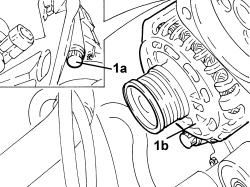
1. Undo the bolts (1a) and move the alternator (1b) aside.
Take care over the positioning of the electrical wiring.
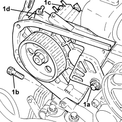
1. Undo the bolts (1a), (1b) and remove the pressure pump mounting (1c) complete with the pressure pump (1d).
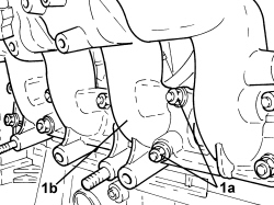
1. Undo the nuts (1a) and remove the intake manifold (1b).
- Remove the gasket.
Refitting
- Place the gasket back in its housing.
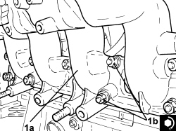
1. Place the intake manifold (1a) in its housing and secure it by tightening the nuts (1b) to the recommended torque.
| Component | Fastening | dia | Value (daNm) | Validity |
|---|---|---|---|---|
| Intake manifold | Nut | M8 | (cylinder head side) 2.3 - 2.8 | 1.9 JTD 8v |
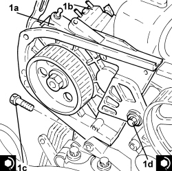
1. Fit the pressure pump mounting (1a) complete with pressure pump (1b) back in its housing and secure it tightening the bolts (1c) and (1d) to the recommended torque.
| Component | Fastening | dia | Value (daNm) | Validity |
|---|---|---|---|---|
| Pressure pump mounting | Bolt (pretreated to be replaced) | M8 | (engine crankcase side) 2.3 - 2.8 | 1.9 JTD 8v |
| Component | Fastening | dia | Value (daNm) | Validity |
|---|---|---|---|---|
| Pressure pump mounting | Bolt | M10 | (cylinder head side) 4.5 - 5.5 | 1.9 JTD 8v |
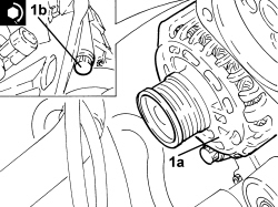
1. Place the alternator (1a) in its housing and fasten it tightening the bolts (1b) to the recommended torque.
| Component | Fastening | dia | Value (daNm) | Validity |
|---|---|---|---|---|
| ALTERNATOR TO BRACKET | Bolt | M12 | 6,3 ÷ 7,6 | 1.9 jtd 16v 1.9 jtd 8v 2.4 jtd 20v |
| Component | Fastening | dia | Value (daNm) | Validity |
|---|---|---|---|---|
| ALTERNATOR TO IE PUMP MOUNTING | Bolt | M12 | 6,3 ÷ 7,6 | 1.9 jtd 16v 1.9 jtd 8v |
- Connect the fuel supply pipe rapid connector, pressure pump side.
- Connect the electrical connection to the fuel pressure regulator on the pressure pump.
- Connect the electrical connection for the pressure relief sensor.
- Refit the electrical wiring and connect the electrical connections to the heater plugs.
Op. 1080D34 ENGINE OIL VAPOUR SEPARATOR - R + R
Op. 1060F50 FUEL RETURN MANIFOLD - R.R.
Op. 1080C80 EXHAUST GAS/WATER HEAT EXCHANGER FOR EGR SYSTEM - R.R
Op. 1048B22 AIR SUPPLY HOSE FROM HEAT EXCHANGER TO INTAKE MANIFOLD - R + R
Op. 1060F30 SINGLE FUEL MANIFOLD PIPE - R.R.
Op. 1060F20 PIPE FROM PRESSURE PUMP TO FUEL MANIFOLD - R.R.
Op. 1060F36 PIPES (ALL) FROM FUEL MANIFOLD TO INJECTOR - R.R.
Op. 1080C24 E.G.R. SYSTEM SOLENOID - R + R
Op. 1060G50 THROTTLE BODY - R.R
Op. 1048B27
Op. 5530B52 BATTERY SUPPORT/DRIP TRAY - R.R
Op. 1032B10 TOOTHED TIMING BELT - R + R FOR TIMING ADJUSTMENT OR REPLACEMENT
Op. 1008A46 POWER UNIT RIGID SUPPORT - TIMING SIDE - R.R.
Op. 1092G20 ENGINE COMPONENT SINGLE BELT FIXED TENSIONER - ONE - R + R
Op. 1032D12 TIMING SYSTEM PROTECTIVE COVER(S) - R + R
Op. 1008B10 POWER UNIT FRONT SUPPORT FLEXIBLE MOUNTING (TIMING SIDE) - REPLACE
Op. 1048A10 AIR FILTER ASSEMBLY - R.R.
Op. 1092A10 CRANKSHAFT PULLEY - R + R
Op. 1092G10 SINGLE ENGINE BELT - R.R
Op. 7055B91 RIGHT FRONT WHEEL ARCH LINER - R.R.
Op. 7055B66 ENGINE COMPARTMENT DUST COVER IN RIGHT FRONT WHEEL ARCH - R.R.
Op. 4450B04 RIGHT FRONT WHEEL - R.R
Op. 0010T20 ENGINE COOLANT - CHANGE
Op. 7055B54 UNDER ENGINE PROTECTION/GUARD - R.R.
Op. 1016A10 SOUND-PROOFING COVER - R.R
- Connect the negative battery terminal.
- Remove the vehicle from the lift.
Parts & tools for this job Staging For 2005 Alfa Romeo 159
- PARTExhaust gasketSearch: Alfa Romeo 159 2005 exhaust gasket
- TOOLPenetrating oilSearch: penetrating oil
- TOOLOBD2 scannerSearch: OBD2 scanner
Links open Amazon search results in a new tab. As an Amazon Associate I earn from qualifying purchases.