
Engine coolant - change
- Make
- Alfa Romeo
- Model
- 159 Factory Service Manual
- Year
- 2005–2011
- Section
- New vehicles and maintenance › Engine coolant - change
ENGINE COOLANT - CHANGE
Procedure for draining the circuit.
- With the engine cold, undo the engine coolant reservoir cap.
Do not remove the tank cap when the engine is warm as there is a risk of scalding.
Op. 7055B54 UNDER ENGINE PROTECTION/GUARD - R.R.
1. Open the radiator coolant drainage tap.
Collect the coolant in a suitable container.
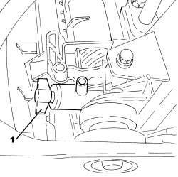
Procedure for refilling the circuit.
- Close the tap on the radiator used for draining the circuit.
1. Open the bleed screw on the water pump rigid inlet pipe.
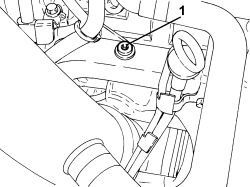
1. Slowly introduce the recommended fluid into the circuit via the filler on the engine coolant supply reservoir keeping the level above the MAX reference until fluid comes out of the bleed, then close the bleed screw.
| Component | Type | Description | Classification | Qty. | Validity |
|---|---|---|---|---|---|
| ENGINE COOLING CIRCUIT | Fluid [I] | Mixture of 50% PARAFLU UP/water | CUNA NC 956-16 - ASTM D 3306 | 7.5 | 1.9 JTD 8V 1.9 JTD 16V |
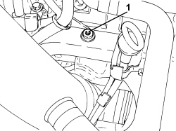
- Complete the introduction of the engine coolant until the MAX reference is reached on the reservoir.
- Start the engine keeping it idling for about 2 minutes and, at the same time, top up, if necessary to the MAX level.
- Fit the engine coolant reservoir cap and tighten.
- Then carry out gradual, periodic acelerations (about every 30 secs.) until the engine speed is 3000 rpm. Repeat this operation until the fan cuts in for about three times.
During this operation keep the climate control system switched off to prevent the fan from coming on for reasons unconnected to the heating of the coolant.
If there is a noticeable drop in the level in the tank below the MIN reference during this stage, let the engine idle and open the cap very carefully, topping up the fluid to the MAX level, then close the cap fully and remove all the air from the system.
- Stop the engine.
- After the above operations and with the engine cold, check the fluid level in the engine coolant reservoir and top up to the MAX notch on the reservoir if necessary.
- At the end of the above operations, make sure that the amount of fluid introduced into the system is at least equal to the amount collected during the draining stage.
Op. 7055B54 UNDER ENGINE PROTECTION/GUARD - R.R.
Procedure for draining the circuit
- With the engine cold, undo the engine coolant reservoir cap.
Do not remove the tank cap when the engine is warm as there is a risk of scalding.
Op. 7055B54 UNDER ENGINE PROTECTION/GUARD - R.R.
1. Open the radiator coolant drainage tap.
Collect the coolant in a suitable container.
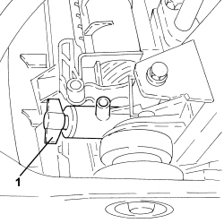
Procedure for refilling the circuit
- Close the tap on the radiator used for draining the circuit.
1. Open the bleed screw on the pipe from the engine to the radiator completely.
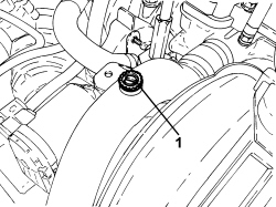
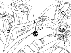
1. Open the bleed screw on the pipe from the radiator to the engine completely.
2. Open the bleed screw on the pipe from the heater to the water-oil heat exchanger completely.
1. Slowly introduce the recommended fluid into the circuit via the filler on the engine coolant supply reservoir keeping the level above the MAX reference until fluid comes out of the bleed, then close the bleed screw.
| Component | Type | Description | Classification | Qty. | Validity |
|---|---|---|---|---|---|
| ENGINE COOLING CIRCUIT | Fluid [I] | Mixture of 50% PARAFLU UP/water | CUNA NC 956-16 - ASTM D 3306 | 8.15 | 1.9 JTS 2.2 JTS |
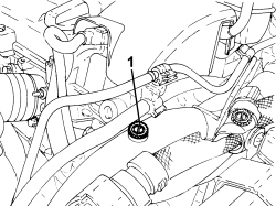
1. Continue introducing fluid until it comes of the bleed, then close the bleed screw.
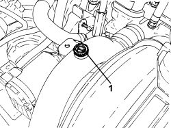
1. Let the fluid level in the reservoir settle down, then close the bleed screw even if only air and not fluid is coming out.
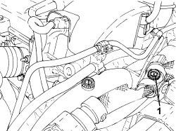
- Fit the engine coolant reservoir cap and tighten.
- Start up the engine and let it idle for about 2 minutes.
- Then carry out gradual, periodic (every 30 secs.) acceleration until the engine speed is around 3/4 of maximum power rpm. Repeat this operation until the fan cuts in for about three times.
During this operation keep the climate control system switched off to prevent the fan from coming on for reasons unconnected to the heating of the coolant.
- Stop the engine.
- After the above operations and with the engine cold, check the engine coolant level in the reservoir and top up to the MAX reference on the reservoir if necessary.
- At the end of the above operations, make sure that the amount of fluid introduced into the system is at least equal to the amount collected during the draining stage.
Op. 7055B54 UNDER ENGINE PROTECTION/GUARD - R.R.
Procedure for draining the circuit.
- With the engine cold, undo the engine coolant reservoir cap.
Do not remove the tank cap when the engine is warm as there is a risk of scalding.
Op. 7055B54 UNDER ENGINE PROTECTION/GUARD - R.R.
1. Open the radiator coolant drainage tap.
Collect the coolant in a suitable container.
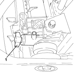
Procedure for refilling the circuit
- Close the tap on the radiator used for draining the circuit.
1. Open the bleed valve on the top left part of the radiator.
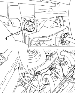
1. Loosen the band (1a) and disconnect the degassing pipe (1b).
Check that the degassing pipe has no residues of fluid in it whatsoever which would prevent the air from escaping when the circuit is refilled. It is advisable to drain the degassing pipe by disconnecting it momentarily from the engine side as well and blowing through with an air jet for a few seconds.
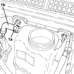
- After having reconnected the degassing pipe, engine side, introduce the recommended fluid to above the MAX reference until fluid comes out of the bleed on the radiator and then close the bleed screw.
| Component | Type | Description | Classification | Qty. | Validity |
|---|---|---|---|---|---|
| ENGINE COOLING CIRCUIT | Fluid [I] | Mixture of 50% PARAFLU UP/water | CUNA NC 956-16 - ASTM D 3306 | 10.3 | 3.2 JTS |
- Continue introducing fluid until it comes out of the degassing pipe, then reconnect it to the reservoir and tighten the band.
During the two stages that have just been described, it is advisable not to stop the operation when the first air bubbles appear, but to let the air/fluid mixture come out for a few seconds.
- Leave the engine coolant level in the reservoir to settle down for a few minutes.
- Fit the engine coolant reservoir cap and tighten.
- Start up the engine and let it idle for about 3 minutes.
- Then carry out gradual, periodic (every 30 secs.) acceleration until the engine speed is around 3/4 of maximum power rpm. Repeat this operation until the fan cuts in for about three times.
1. Open the bleed screw letting the air that has accumulated at the top to escape.
- Close the bleed screw as soon as fluid comes out.
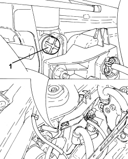
During this operation keep the climate control system switched off to prevent the fan from coming on for reasons unconnected to the heating of the coolant.
- Stop the engine.
- After the above operations and with the engine cold, check the engine coolant level in the reservoir and top up to the MAX reference on the reservoir if necessary.
- At the end of the above operations, make sure that the amount of fluid introduced into the system is at least equal to the amount collected during the draining stage.
Op. 7055B54 UNDER ENGINE PROTECTION/GUARD - R.R.
Procedure for draining the circuit.
- With the engine cold, undo the engine coolant reservoir cap.
Do not remove the tank cap when the engine is warm as there is a risk of scalding.
Op. 7055B54 UNDER ENGINE PROTECTION/GUARD - R.R.
1. Open the radiator coolant drainage tap.
Collect the coolant in a suitable container.
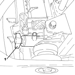
Procedure for refilling the circuit.
- Close the tap on the radiator used for draining the circuit.
1. Open the bleed valve on the return pipe from the radiator.
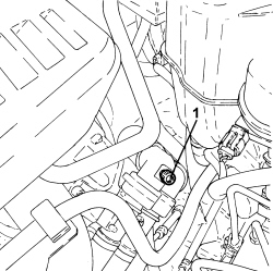
1. Open the bleed valve on the top left part of the radiator.
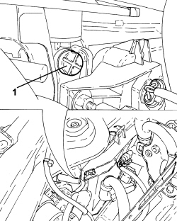
1. Open the bleed valve on the rigid return pipe to the water pump.
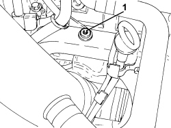
- Slowly introduce the recommended fluid into the circuit via the filler on the engine coolant supply reservoir keeping the level above the MAX reference until fluid comes out of the bleeds opened previously, then close the bleed screws.
| Component | Type | Description | Classification | Qty. | Validity |
|---|---|---|---|---|---|
| ENGINE COOLING CIRCUIT | Fluid [I] | Mixture of 50% PARAFLU UP/water | CUNA NC 956-16 - ASTM D 3306 | 7.35 | 2.4 JTD 20V |
- Complete the introduction of engine coolant until the MAX reference on the reservoir is reached.
1. Loosen the band (1a), disconnect the degassign pipe (1b) and introduce it directly into the engine coolant reservoir filler.
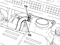
- Start up the engine and let it idle for about 2 minutes.
- Later on, accelerate and make sure that the water is circulating in the circuit; this can be ascertained by the presence of a jet of water coming from the degassing pipe submerged in the reservoir.
- If the water is not circulating, repeat the bleeding operations using the dedicated screws described previously.
- At the same time top up the fluid, if necessary, to the MAX reference.
- Restore the connection for the degassing pipe on the reservoir and tighten the band.
- Fit the engine coolant reservoir cap and tighten.
- Then accelerate gradually and periodically (about every 30 seconds) until a speed of 3500 rpm is reached. Repeat this operation until the fan cuts in for about three times.
During this operation keep the climate control system switched off to prevent the fan from coming on for reasons unconnected to the heating of the coolant.
- If the level in the reservoir drops considerably during this stage, restore the engine idle speed and open the filler cap very carefully and top up to the MAX level; then close the cap completely and finish the bleeding of the air from the engine cooling system.
- Stop the engine for around 1 minute and wait for any air bubbles from the thermostat to rise towards the engine coolant reservoir.
- Start the engine again and carry out another cycle of accelerations and fan engagements.
- Stop the engine and wait for a sufficient drop in the engine coolant temperature.
- After the above operations, check the fluid level in the reservoir and top up to the MAX notch on the reservoir if necessary.
- At the end of the above operations, make sure that the amount of fluid introduced into the system is at least equal to the amount collected during the draining stage.
Parts & tools for this job Staging For 2005 Alfa Romeo 159
- PARTEngine gasket setSearch: Alfa Romeo 159 2005 engine gasket set
- TOOLTorque wrenchSearch: 3/8 inch torque wrench
- TOOLFeeler gauge setSearch: feeler gauge set
Links open Amazon search results in a new tab. As an Amazon Associate I earn from qualifying purchases.