
General remarks - clutch
- Make
- Alfa Romeo
- Model
- 159 Factory Service Manual
- Year
- 2005–2011
- Section
- General › General remarks - clutch
GENERAL REMARKS - CLUTCH
CLUTCH - FLYWHEEL ASSEMBLY
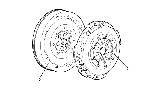
1. Clutch
2. Flywheel
The clutch-flywheel system on the 1.9 JTS/2.2 JTS engines is supplied by SACHS and has the following specifications:
- dry, single plate clutch with thrust operation
- dual mass type shock absorbing flywheel.
Clutch assembly
Dry, single plate type clutch with hydraulically operated thrust release, coaxial internal actuator and XTend plate wear recovery device.
Xtend plate wear recovery device
The automatic recovery of the clutch plate wear clearance makes it possible to keep the clutch pedal free play constant.
The automatic wear recovery mechanical device known as XTend has the following specifications:
- independent of tolerances and does not require adjustment;
- exact recovery of plate wear;
- robust system with simple mechanical parts.
The device consists of:
- compression spring;
- clip;
- positioning rings;
- adjuster;
- adjuster traction spring;
- traction spring for positioning rings;
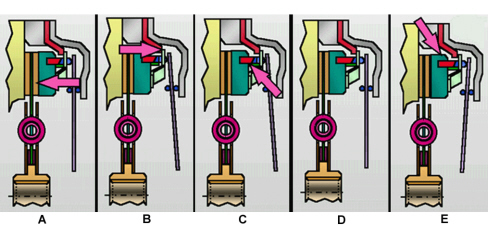
Operating principle
During usage the thrust plate and the recovery mechanism move towards the flywheel (A).
The slit corresponding exactly to the wear of the seal (B) forms under the compression spring.
The adjuster slides and detects this wear (C).
With the clutch released (D), the lower positioning ring slides and closes the slit under the compression spring detected by the adjuster (E).
On the new engagement, the wear is recovered and the diaphragm spring returns to its original position.
Driven friction plate
The driven disc fitted on the Sachs flywheel/clutch assembly is the pre-damping flexible type which contains springs with a flexible coupling function.
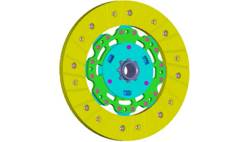
The benefits of adopting this component are:
- reduction in hub wear;
- decrease in angular and radial lack of balance between the engine and gearbox;
- improved uncoupling in neutral with the use of a reduced travel pre-shock absorber;
- reduction in radial forces caused by offset between crankshaft and gearbox.
Twin mass damping flywheel
This flywheel is the twin mass damping type consisting of two masses, one forming one piece with the crankshaft and the other with the gearbox main shaft, via the clutch plate. There is a double rigidity flexible torsional damping system between the two masses made up of two systems with differing flexible rigidity springs and an epicyclic gear immersed in grease. The feature of this flywheel is the variation in the torsional resonance which, compared with a normal flywheel, is below the engine operating speed and improves driving comfort and reduces the transmission of irregular loads to the gearbox.
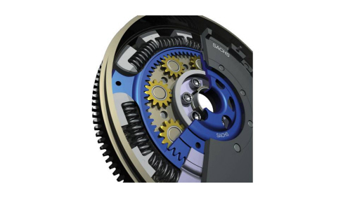
The mass on the crankshaft contributes to the inertia of the engine, whilst the other mass on the gearbox increases the transmission inertia; as there is a reduction in the engine inertia and an increase in the transmission inertia, with the mass (and consequently the flywheel inertia) being equal, thanks also to the connection between the two masses produced by the springs, there is a considerable reduction in the vibrations produced by the engine at the transmission especially at low engine revs when vibrations are greater. This allows an improvement in driving comfort especially at low engine speeds.
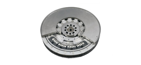
The special features of the flywheel are:
- variable damping configuration;
- arrangement of springs in series;
- mechanical protection to prevent the springs from locking;
- combination of two main principles for damping;
- friction for pads on main flywheel;
- damping proportional to the speed of the planet wheels;
- the system does not require a further damping element;
- long operating life due to loading with grease (lubrication for life);
- neutral behaviour during ignition, shortened switching on and switching off.
Compared with a traditional transmission this flywheel makes it possible to reduce engine revs oscillations during the transmission of power to the gearbox assembly, extending the resonance range (which causes the possible phenomenons of vibrations or roughness in transmission) to a sufficiently low engine speed so as not to interfere with the speed range usually used when driving.
Operation
The kinematic route of the power transmission is illustrated in the diagram.
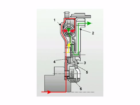
1. Main flywheel
2. Secondary flywheel
3. Wheel
4. Planet wheel
5. Axial bearing
6. Radial bearing
The crankshaft transmits the power to the main flywheel.
The pads receive the power from the main flywheel and transfer it to the springs;
The spring system acts as a damper for the torque variations.
The pads-springs system transmits the power to the wheel which, in turn, transmits it to the secondary flywheel.
The epicyclic system consists of the gear train carrier (main flywheel), the ring gear with internal teeth (wheel) and eight satellite gears.
This gearing behaves like a second damping element as the system is immersed in grease and the satellite wheels have a rotation inertia.
With this type of flywheel the damping of the torque fluctuations are in two stages, capable of reducing the vibrations and roughness of the transmission of power more effectively and with better direction.
CLUTCH ASSEMBLY
The clutch-flywheel system on the 1.9 JTD engine is supplied by VALEO and has the following specifications:
Dry, single plate type clutch with hydraulically operated thrust release, coaxial internal actuator; outer diameter 240 mm; spring loading 640 daN.
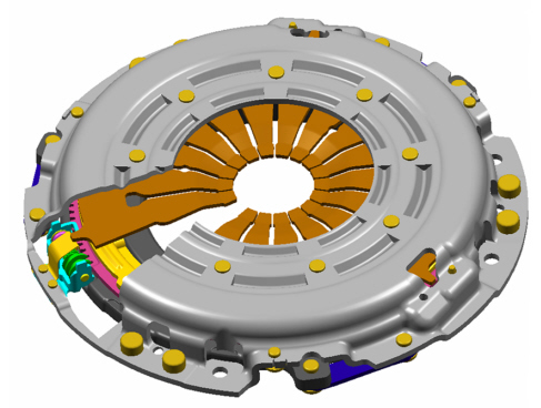
"sat" disc wear recovery system (self adjusting technology)
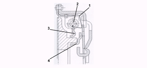
The clutch supplied by Valeo has a mechanical device for recovering friction disc wear known as "SAT" which exploits the rotation principle between the two rings with inclined adjacent planes. The components for this system are illustrated in the section below.
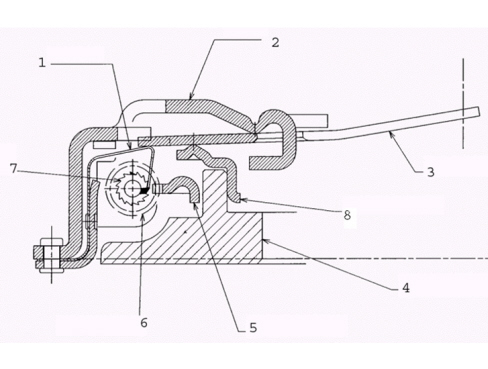
1. Toothed plate
2. Clutch cover
3. Diaphragm spring
4. Pressure plate
5. Toothed sector with inclined plane
6. Worm screw
7. Gear
8. Thrust ramp with inclined plane
SYSTEM OPERATING PRINCIPLE
ENGAGEMENT WHEN DISC IS NEW: the toothed plate (1) is pressed against the top of the gear tooth (2);
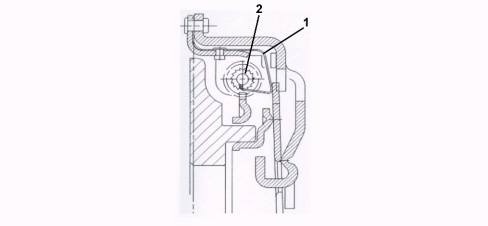
RELEASE WHEN DISC IS NEW: the toothed plate (1) rests on the clip incorporated in the cover (2); in this position it is still in contact with the previous tooth;
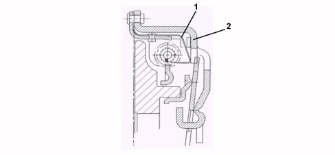
ENGAGEMENT WHEN DISC IS USED: the toothed plate (1) presses the tooth for the gear (2) with a value corresponding to the wear of the friction disc;
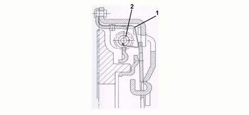
RELEASE WHEN DISC IS USED: the toothed plate (1) being able to move because the diaphragm spring (2) is released, slides on the next gear tooth (3); it is now in a position to rotate the gear for the next engagement operation;
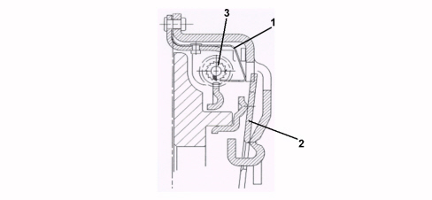
NEXT ENGAGEMENT: the toothed plate (1) presses the tooth for a distance corresponding to the height of the tooth; this operation rotates the gear (2) and, at the same time, the toothed sector (3) and consequently the thrust ramp (4), by means of the system of inclined planes; at the end of the engagement the ramp is moved axially by the exact value of the wear to be recovered.
Driven friction plate
The friction disc contains a spring system which acts as flexible coupling; the connection betwen the propeller shaft and the gearbox is made through a splined hub. The side facing the flywheel is shown in the photo.
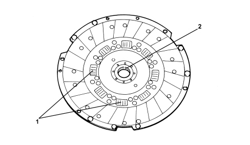
1. Flexible coupling springs
2. Splined hub
CLUTCH ASSEMBLY
The clutch-flywheel system is supplied by VALEO. Its features are as follows:
Dry, single plate type clutch with hydraulically operated thrust release, coaxial internal actuator; outer diameter 240 mm; spring loading 640 daN.
"sat" disc wear recovery system (self adjusting technology)
The clutch supplied by Valeo has a mechanical device for recovering friction disc wear known as "SAT" which exploits the rotation principle between the two rings with inclined adjacent planes. The components for this system are illustrated in the section below.
1. Toothed plate
2. Clutch cover
3. Diaphragm spring
4. Pressure plate
5. Toothed sector with inclined plane
6. Worm screw
7. Gear
8. Thrust ramp with inclined plane
SYSTEM OPERATING PRINCIPLE
ENGAGEMENT WHEN DISC IS NEW: the toothed plate (1) is pressed against the top of the gear tooth (2);
RELEASE WHEN DISC IS NEW: the toothed plate (1) rests on the clip incorporated in the cover (2); in this position it is still in contact with the previous tooth;
ENGAGEMENT WHEN DISC IS USED: the toothed plate (1) presses the tooth for the gear (2) with a value corresponding to the wear of the friction disc;
RELEASE WHEN DISC IS USED: the toothed plate (1) being able to move because the diaphragm spring (2) is released, slides on the next gear tooth (3); it is now in a position to rotate the gear for the next engagement operation;
NEXT ENGAGEMENT: the toothed plate (1) presses the tooth for a distance corresponding to the height of the tooth; this operation rotates the gear (2) and, at the same time, the toothed sector (3) and consequently the thrust ramp (4), by means of the system of inclined planes; at the end of the engagement the ramp is moved axially by the exact value of the wear to be recovered.
Driven friction plate
The friction disc contains a spring system which acts as flexible coupling; the connection betwen the propeller shaft and the gearbox is made through a splined hub. The side facing the flywheel is shown in the photo.
1. Flexible coupling springs
2. Splined hub
Parts & tools for this job Staging For 2005 Alfa Romeo 159
- PARTClutch kitSearch: Alfa Romeo 159 2005 clutch kit
- TOOLClutch alignment toolSearch: clutch alignment tool
- FLUIDGear oilSearch: Alfa Romeo 159 manual gearbox oil
Links open Amazon search results in a new tab. As an Amazon Associate I earn from qualifying purchases.