
Introduction - intake and exhaust manifolds
- Make
- Alfa Romeo
- Model
- 159 Factory Service Manual
- Year
- 2005–2011
- Section
- Inlet and exhaust manifolds › Introduction - intake and exhaust manifolds
INTRODUCTION - INTAKE AND EXHAUST MANIFOLDS
INTAKE MANIFOLD SPECIFICATIONS
The continuous adjustment swirl valves are incorporated in the intake manifold inside the four additional intake ducts.
The swirl valves are operated by means of an electronically controlled actuator. The actuator moves an adjustment rod which operates on the swirl valves via an idler.
The swirl valves are connected to one another by linkage.
Thanks to the geometric shape of the four additional intake ducts and the swirl valves the fresh gases create a vortex and are directed in the best possible way to the combustion chamber. The filling of the cylinders is therefore excellent.
The continuous adjustment of the swirl valves makes it possible to produce optimum turbulence for all engine speed and load conditions.
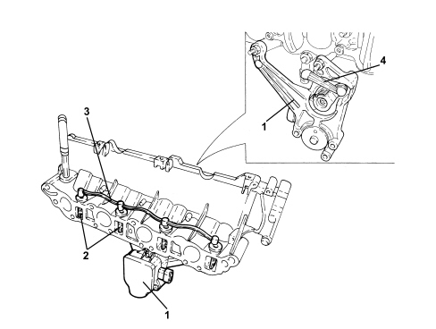
1. Swirl valve electric control actuator
2. Swirl valves
3. Swirl valve connecting linkage
4. Swirl valve control lever
It is possible to adapt the turbulence of the fresh gases inside the combustion chambers to the respective engine load conditions by adjusting the swirl valves.
High turbulence is created in the combustion chamber by closing the swirl valves, thereby allowing an optimum fuel mixture to be injected at low engine revs.
Thanks to this optimum mixture of fuel with fresh gases the emission of pollutant substances is greatly reduced.
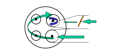
At a higher number of engine revs the swirl valves are completely open. This produces a reduction in the turbulence of the fresh gases and increases the degree of filling.
A higher degree of cylinder filling produces an increase in engine power.
INTAKE MANIFOLD SPECIFICATIONS
The continuous adjustment swirl valves are incorporated in the intake manifold inside the four additional intake ducts.
The swirl valves are operated by means of an electronically controlled actuator. The actuator moves an adjustment rod which operates on the swirl valves via an idler.
The swirl valves are connected to one another by linkage.
Thanks to the geometric shape of the four additional intake ducts and the swirl valves the fresh gases create a vortex and are directed in the best possible way to the combustion chamber. The filling of the cylinders is therefore excellent.
The continuous adjustment of the swirl valves makes it possible to produce optimum turbulence for all engine speed and load conditions.
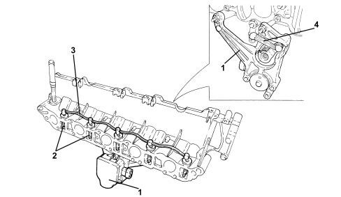
1. Swirl valve electric control actuator
2. Swirl valves
3. Swirl valve connecting linkage
4. Swirl valve control lever
It is possible to adapt the turbulence of the fresh gases inside the combustion chambers to the respective engine load conditions by adjusting the swirl valves.
High turbulence is created in the combustion chamber by closing the swirl valves, thereby allowing an optimum fuel mixture to be injected at low engine revs.
Thanks to this optimum mixture of fuel with fresh gases the emission of pollutant substances is greatly reduced.
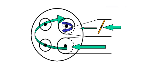
At a higher number of engine revs the swirl valves are completely open. This produces a reduction in the turbulence of the fresh gases and increases the degree of filling.
A higher degree of cylinder filling produces an increase in engine power.
The intake manifold is made from aluminium, in a single component, tightened to the cylinder heads by six bolts; it distributes the intake air that flows through the 72 mm electronic throttle body to the cylinders.
The connection for the brake servo pipe, those for the oil vapour recovery from the left head and for the petrol vapour recovery and the intake air pressure sensor are located on the intake chamber.
INLET MANIFOLD
The engine has a two stage modular intake manifold made from plastic.
Depending on the operating conditions, the intake air is directed via two different length intake routes. The switch from one intake route to the other takes place at high engine loads and at engine speeds of between 1500 and 4200 rpm through the rotation of a roller switch (2) incorporated in the intake manifold. The use of a roller switch for controlling the intake manifolds involves considerable advantages compared with the usual turbulence valves. In this way, for example, the switching resistances at very high speeds in the plastic intake module are considerably reduced and there is a very good seal in the intake manifolds when closed.
The air is introduced into the intake manifold via the throttle body at the side of the actual manifold.
This position allows the optimum arrangement of the ducts for the individual arms of the intake manifolds with a reduction in load leaks in the section from the air filter to the intake valves. In this way it has also been possible to keep the section of the pipes constant for the entire length of the intake section.
The engine management control unit sends a signal to the normally closed electromagnetic valve (1); the latter, on opening, allows the flow of the vacuum from the intake manifold to the actuator (2) which operates the shaft (3) which controls the roller switch.
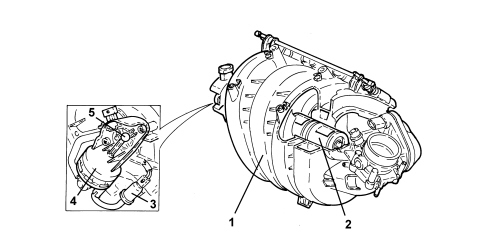
1. Modular intake manifold
2. Roller switch
3. Electropneumatic valve
4. Pneumatic actuator
5. Roller switch control shaft
EXHAUST MANIFOLD
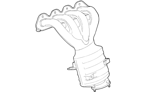
Made from pressed steel it incorporates the catalytic converter for controlling exhaust emissions.
The special 4 in 1 structure allows the even distribution of the exhaust gases at the catalytic converter inlet where the Lambda sensor is found.
The oscillations of the exhaust manifold are opposed by a special bracket fastened to the engine block.
Parts & tools for this job Staging For 2005 Alfa Romeo 159
- PARTExhaust gasketSearch: Alfa Romeo 159 2005 exhaust gasket
- TOOLPenetrating oilSearch: penetrating oil
- TOOLOBD2 scannerSearch: OBD2 scanner
Links open Amazon search results in a new tab. As an Amazon Associate I earn from qualifying purchases.