
E7050 Automatic transmission (Selespeed)
- Make
- Alfa Romeo
- Model
- 156 Factory Service Manual
- Year
- 1997–2002
- Section
- Car electronic systems › E7050 Automatic transmission (Selespeed)
E7050 Automatic transmission (Selespeed)
Description
A control system called SELESPEED supervises and governs the operation of the manual gearbox via an electrohydraulic device.
An electronic control unit manages a complex operating logic which enables the gearbox to be used in both 'semi-automatic' conditions, in which the driver manages the engagement of the gears using the lever or the two steering wheel buttons, and automatic 'CITY' mode which delegates gear change management to the electronic system.
The electronic control unit dialogues with the engine management control unit via two dedicated lines (CAN), and receives the rpm, engine torque and engine temperature signals.
The control unit drives, by means of a complex operating logic, an electrohydraulic unit located on the gearbox, via a specific electric pump.
For more details, Characteristic of working principle 2127 Hydraulic transmission external linkage .
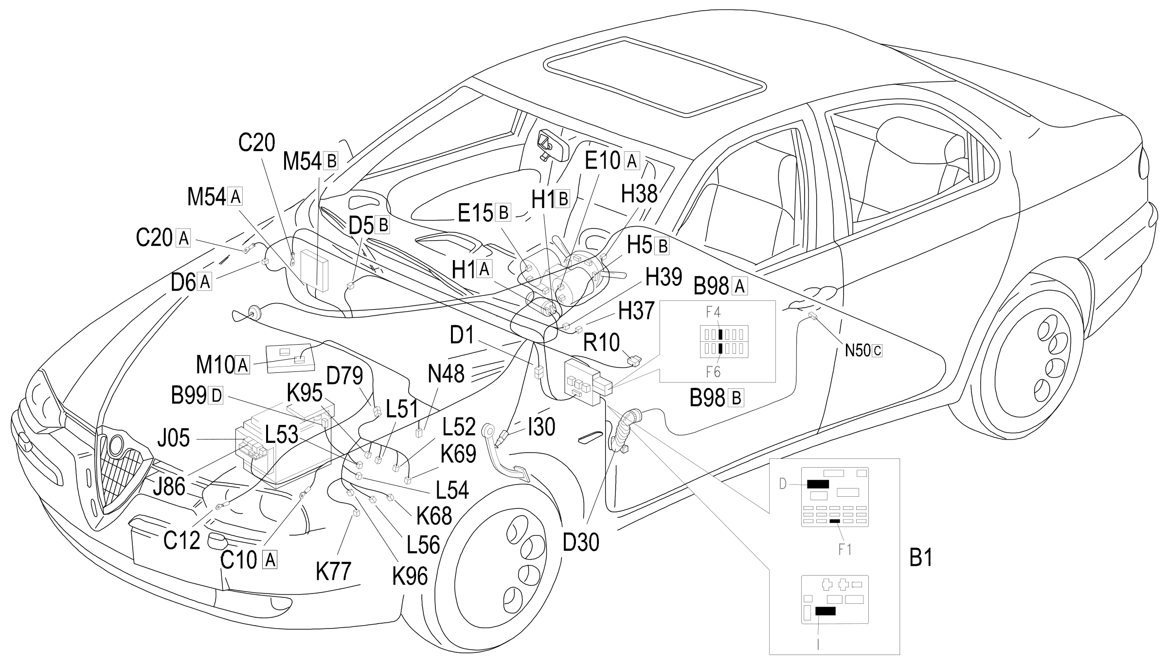
The system is also controlled by means of two relays located in the engine compartment near the battery.
The supply lines to the control unit and the various system components (sensors and actuators) are protected by two specific maxifuses and other jumper fuses, located next to the junction unit.
Description of operation
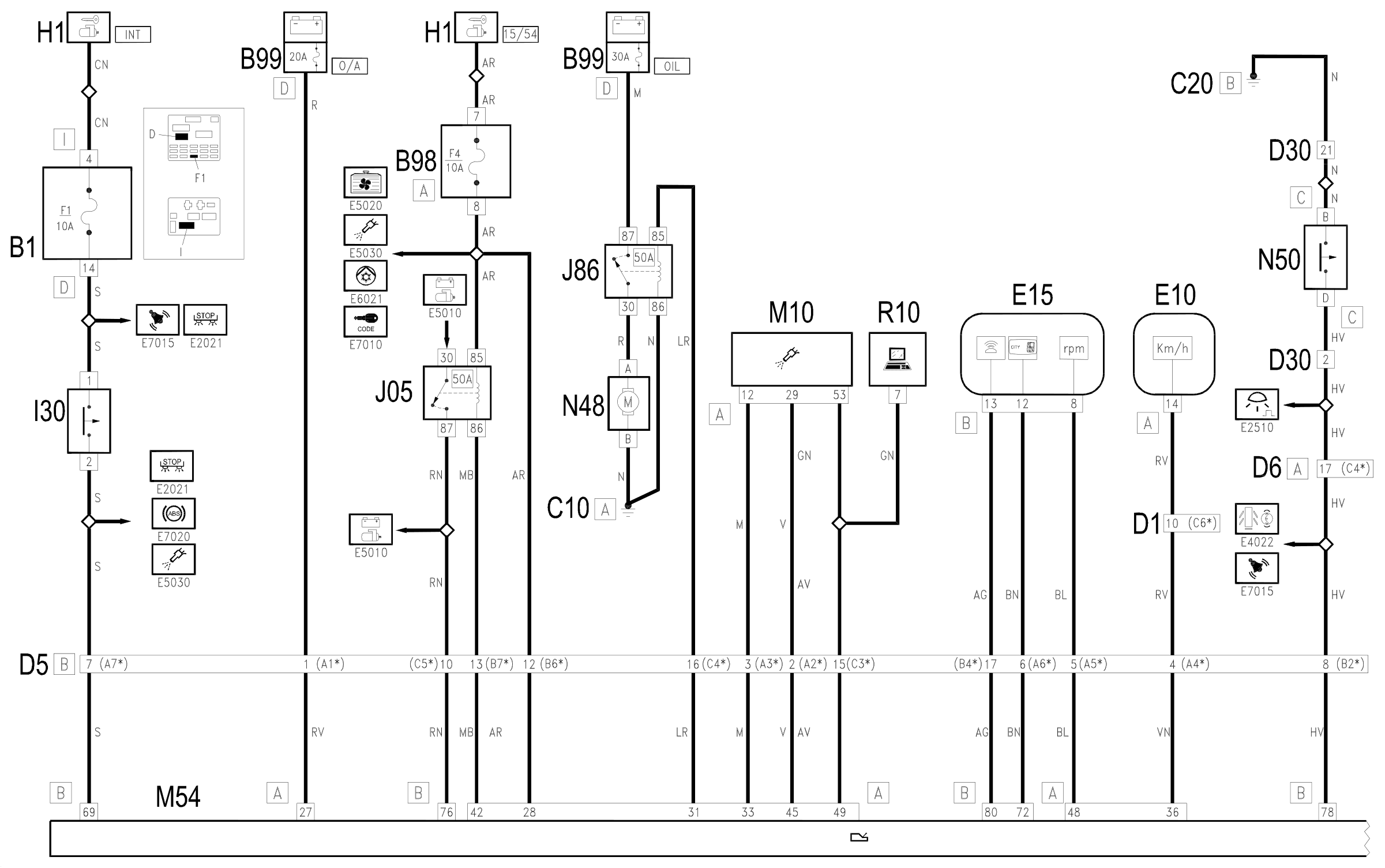
The SELESPEED control unit M54 monitors and controls the entire gearbox management system.
The control unit is supplied directly by the battery, via the line of the maxifuse O/A located on the battery (connector B99 D), at pin 27 of connector A of M54.
The supply controlled by the ignition (15/54) reaches pin 28 of connector A of M54, via the line protected by fuse F4 of supplementary fuse box B98 A.
Pins 1 and 2 of connector A of M54 are earthed.
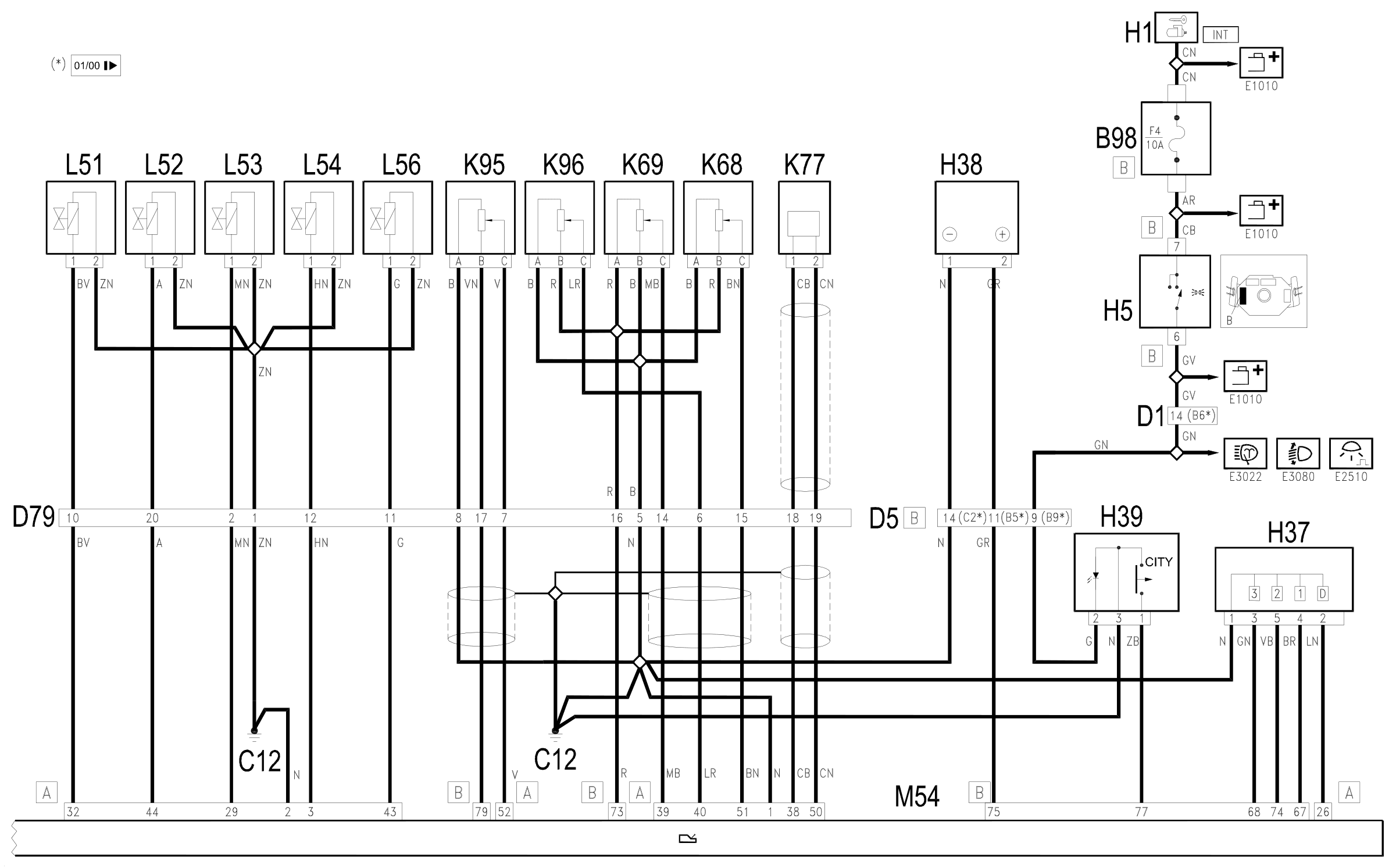
A set of sensors and potentiometers on the gearbox informs the control unit as to which gear is engaged:
the potentiometers are supplied from pin 73 of connector B; the gear selection potentiometer K68 returns a signal to pin 51 of connector A; the gear engagement potentiometer K69 returns a signal to pin 39 of connector A; the hydraulic unit oil pressure sensor K96 returns a signal to pin 40 of connector A.
The clutch position potentiometer K95 is supplied from pin 79 of connector B and returns a signal to pin 52 of connector A.
Pins 38 and 50 of connector A M54 are connected to the car speed sensor (gearbox output) K77.
Pin 36 of connector A is connected to instrument E10 from which it receives the speedometer signal (car speed).
Pin 48 of connector A is connected to instrument E15 from which it receives the engine rpm signal.
The gear control unit H37 is connected to the control unit M54 to signal the request to engage a gear: these signals are sent to pins 67, 74, 68 of connector B of M54; and to pin 26 of connector A to signal the request for gears 1, 2, 3 and D respectively.
The selector H39 allows the CITY mode to be selected; it is connected to the M54 control unit at pin 77 of connector B; (the display is also lit up with the side lights on (line coming from steering column switch unit H5).
The steering wheel controls H38 send signals to pin 75 of connector B of M54.
Pin 69 of connector B of M10 receives the signal coming from the brake lights switch I30, with the supply controlled by the ignition (INT) from fuse F1 of the junction unit B1 Wiring diagram E2021 STOP LIGHT .
In accordance with the operating logic, the control unit controls the electrohydraulic unit located on the gearbox which effects the gear change: the electric pump N48, which keeps the oil in the hydraulic unit under pressure, is controlled from pin 31 of connector A.
The pump N48 is controlled by a specific relay J86 (supplied by the line of the specific maxifuse F/P located on the battery (connector B99 D).
The control unit then controls the opening of the hydraulic unit solenoids:
- the two gear engagement solenoids L51 and L52 are controlled from pins 32 and 44 of connector A of M54;
- the two gear selection solenoids L53 and L54 are controlled from pins 29 and 3 of connector A of M54;
- the clutch control solenoid L56 is controlled from pin 43 3 of connector A of M54.
A safety signal comes from pin 42 of connector A of M54 for the starting enablement relay J05 which gives starting enablement, pin 50 of the starter motor A20; the signal requesting starting reaches pin 76 of connector B Wiring diagram E5010 IGNITION AND RECHARGING .
The control unit M54 also manages the door open buzzer: the driver's door open signal - catch N50 - reaches pin 78 of connector B of M54; the control for the buzzer, located in instrument E15 departs from pin 80 of connector B.
The control unit M54 has a self-test system, which can be used by connecting the unit to the connector R10: this receives signals from pin 49 of connector A of M54(the serial line is shared with the engine control unit M10).
The same self-test also sends signals for the 'automatic gearbox fault' warning light. located in the instrument E15, via the same line - coming out of pin 72 of connector B - it is used for the gear indication display on the instrument itself.
The control unit M54 is connected to the engine management control unit M10: this connection is made via the CAN line from pins 33 and 45 of connector B of M54 and is connected to pins 12 and 29 of connector A of M10.
Wiring diagram
Components
| Code | Component | See |
|---|---|---|
| B01 | Junction unit | description 5505A |
| B42 | Automatic transmission supply fuse | |
| B98 | Supplementary fuse box | description 5505A |
| B99 | Maxifuse box on battery | |
| C10 | Front left earth | description 5505A |
| C12 | ABS front earth | description 5505A |
| C20 | Passenger side dashboard earth | description 5505A |
| D01 | Front / dashboard connection | |
| D05 | Front / ABS couping | |
| D30 | Rear / front door connection left | |
| D79 | Transmission sensor junction | |
| D83 | I.e. / transmission connection | |
| E10 | Speedometer | description 5560B |
| E15 | Rev counter | description 5560B |
| H01 | Ignition switch | description 5520A |
| H05 | Steering column switch unit | description 5550A |
| H37 | Gear controls | description 2127A |
| H38 | Gear controls on steering wheel | |
| H39 | CITY function switch | description 2127E |
| H49 | Driving mode selection switch (A.T.) | |
| I30 | Brake pedal switch | description 5550D |
| J05 | Starting enablement relay | |
| J86 | Automatic transmission relay | |
| K68 | Speed selection potentiometer | description 2127E |
| K69 | Gear shift potentiometer | description 2127E |
| K77 | Transmission output speed sensor | description 2127E |
| K78 | Transmission input speed sensor | description 2127E |
| K95 | Clutch position potentiometer | description 2127E |
| K96 | Pressure sensor on transmission | description 2127E |
| L50 | Automatic transmission solenoid unit | description 2127C |
| L51 | Solenoid 1 (gear shift) | description 2127E |
| L52 | Solenoid 2 (gear shift) | description 2127E |
| L53 | Solenoid 3 (gear selection) | description 2127E |
| L54 | Solenoid 4 (gear selection) | description 2127E |
| L55 | Transmission release electromagnet | description 2127C |
| L56 | Clutch control solenoid | description 2127E |
| M10 | Engine management ECU | |
| M10 | Engine management control unit | description 1056B |
| M54 | Selespeed transmission control unit | description 2127E |
| M55 | Automatic transmission control unit | description 2135B |
| N48 | Automatic transmission pump | description 2127C |
| N49 | Automatic transmission fluid fan | description 7010N |
| N50 | Right front door lock left | description 7005N |
| R10 | Multiple tester connection |
Component location
Parts & tools for this job Staging For 1997 Alfa Romeo 156
- PARTTransmission filter kitSearch: Alfa Romeo 156 1997 transmission filter kit
- FLUIDAutomatic transmission fluidSearch: Alfa Romeo automatic transmission fluid
- TOOLFluid transfer pumpSearch: fluid transfer pump
Links open Amazon search results in a new tab. As an Amazon Associate I earn from qualifying purchases.