
Front Wipers (page 4 of 4)
- Make
- Land Rover
- Model
- Range Rover L322 Range Rover System Description and Operation
- Section
- Description
WIPERS AND WASHERS
DESCRIPTION AND OPERATION
84-11
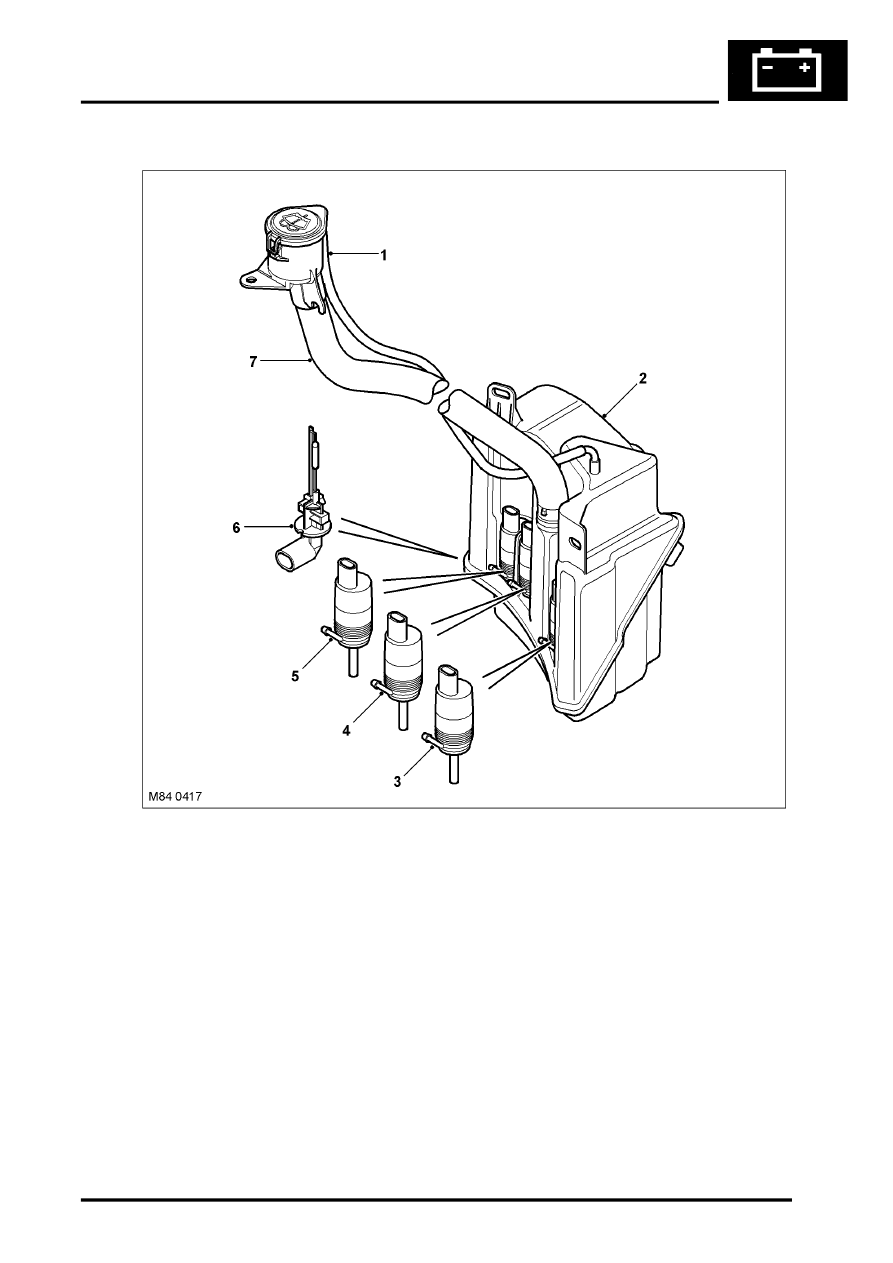
Washer Reservoir and Pumps
1 Breather tube
2 Reservoir
3 Rear washer pump
4 Front washer pump
5 Headlamp washer pump
6 Fluid level sensor
7 Filler tube and cap
The windscreen washer system comprises a reservoir, a washer pump, two washer jets and hoses.
The plastic, moulded reservoir is located in the LH wheel arch, behind the liner and has a capacity of 8.8 pints (5 litres).
It is secured to the body and front panel with bolts and washers. A boss on the reservoir locates in a slot in the front
panel and provides additional support.
The reservoir has three recessed holes on its rear face which provide location for the front, rear and headlamp washer
pumps. The pumps are push fitted into grommets which seal the pumps in their locations. A hole in the top of the
reservoir allows for the fitment of a flexible filler tube. The hose is routed into the left hand side of the engine
compartment and is sealed with a rubber cap. A breather hose is fitted into an elbow on the top of the reservoir and
is routed alongside the filler and secured in a clip near the filler cap in the engine compartment.
A hole in the base of the reservoir provides the location for the fluid level sensor. The hole provides access to an
internal tube in side the reservoir, into which the sensor is fitted. The sensor has two pegs which positively locate the
sensor in the reservoir when turned through 90
°
.
Parts & tools for this job Staging For Land Rover Range Rover
- PARTWiper bladesSearch: Land Rover Range Rover wiper blades
- PARTWasher pumpSearch: Land Rover Range Rover washer pump
Links open Amazon search results in a new tab. As an Amazon Associate I earn from qualifying purchases.