
Transfer Box ECU (page 2 of 2)
- Make
- Land Rover
- Model
- Range Rover L322 Range Rover System Description and Operation
- Section
- Description
TRANSFER BOX
41-18
DESCRIPTION AND OPERATION
Default/Limp Home Strategy
If a fault occurs with the transfer box, the transfer box ECU or one of the required input signals, i.e.; road speed signal,
the ECU records an error code and the transfer box low range 'mountain' symbol in the instrument pack flashes
permanently.
As a default setting, the ECU will attempt to engage high or low range in order to allow the vehicle to be driven to a
Land Rover dealer for repair. To ensure a range is engaged, the ignition must be switched off and then on again (timed
shift performs this without ignition cycling). This causes the ECU to power the actuator and engage the previously
selected range.
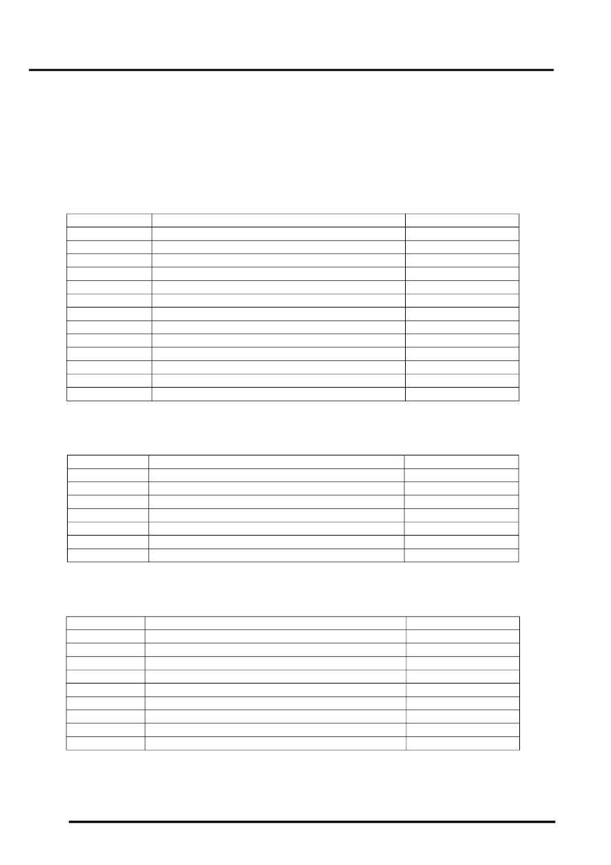
Transfer Box Harness Connector C1319 Pin Details
Transfer Box Harness Connector C1854 Pin Details
Transfer Box Harness Connector C1855 Pin Details
Pin No.
Description
Input/Output
1 to 6
Not used
–
7
Neutral request (when fuse 37 installed)
Input
8
High/Low range switch
Input
9 to 12
Not used
–
13
CAN bus low
Input/Output
14
Not used
–
15
Ignition power supply
Input
16
Not used
–
17 and 18
Not used
–
19
Diagnostic ISO 9141 K line bus
Input/Output
20 to 25
Not used
–
26
CAN bus high
Input/Output
27 to 52
Not used
–
Pin No.
Description
Input/Output
1 to 5
Not used
–
6
Actuator potentiometer 5 volt reference voltage
Output
7 to 9
Not used
–
10
Actuator potentiometer signal
Input
11 to 16
Not used
–
17
Actuator potentiometer ground
–
18 to 40
Not used
–
Pin No.
Description
Input/Output
1
Not used
–
2
Ground
–
3
Ground
–
4
Motor A supply/ground
Input/Output
5
Permanent battery power supply
Input
6
Permanent battery power supply
Input
7
Motor A supply/ground
Input/Output
8
Motor B supply/ground
Input/Output
9
Motor B supply/ground
Input/Output
Parts & tools for this job Staging For Land Rover Range Rover
- TOOLTorque wrenchSearch: 3/8 inch torque wrench
- TOOLSocket setSearch: socket set metric
- BOOKHaynes manualSearch: Haynes manual Land Rover Range Rover
Links open Amazon search results in a new tab. As an Amazon Associate I earn from qualifying purchases.