
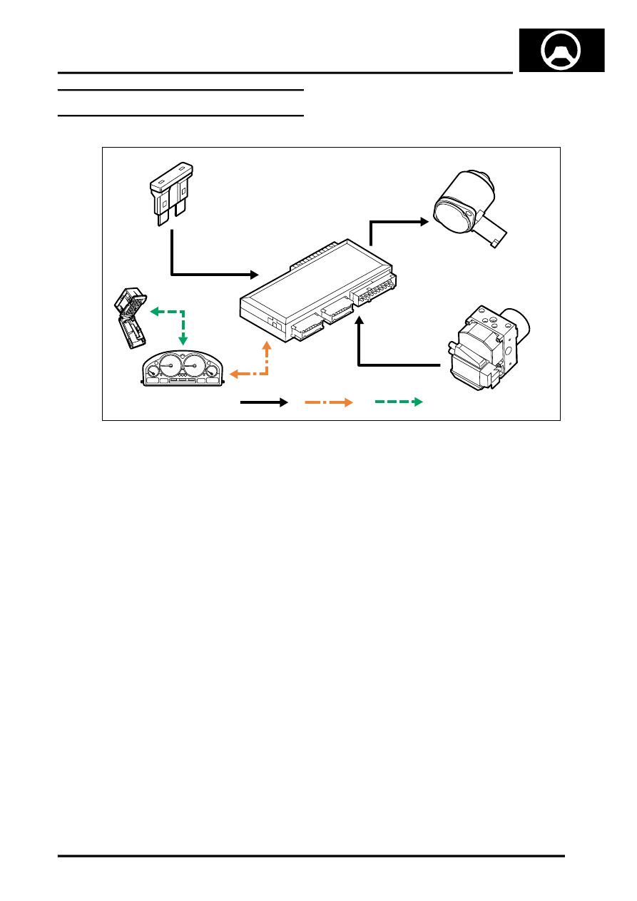
Steering Control Diagram – Servotronic
- Make
- Land Rover
- Model
- Range Rover L322 Range Rover System Description and Operation
- Section
- Steering Control Diagram – Servotronic
‹ Prev Steering Component Location – V8Next › Steering Control Diagram – Column Adjustment – Without Memory
STEERINGSteering Control Diagram – Servotronic
STEERING
DESCRIPTION AND OPERATION
57-3
Steering Control Diagram – Servotronic
A = Hardwired; B = K Bus; C = Diagnostic DS2 bus
1 Fuse 5A – Battery permanent supply
2 Servotronic valve
3 Body Control Unit (BCU)
4 ABS ECU
5 Instrument pack
6 Diagnostic socket
M57 1179A
1
A
2
3
4
5
6
B
C
‹ Prev Steering Component Location – V8Next › Steering Control Diagram – Column Adjustment – Without Memory
Parts & tools for this job Staging For Land Rover Range Rover
- TOOLTie rod end toolSearch: tie rod end puller
- TOOLBall joint separatorSearch: ball joint separator
- FLUIDPower steering fluidSearch: Land Rover power steering fluid
Links open Amazon search results in a new tab. As an Amazon Associate I earn from qualifying purchases.