
Immobilisation Control Diagram – Diesel
- Make
- Land Rover
- Model
- Range Rover L322 Range Rover System Description and Operation
- Section
- Immobilisation Control Diagram – Diesel
SECURITYImmobilisation Control Diagram – Diesel
SECURITY
86-5-18 DESCRIPTION AND OPERATION
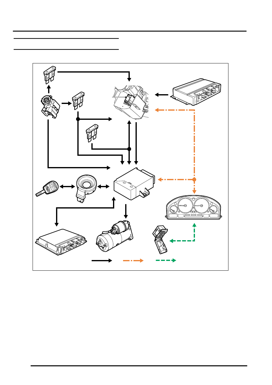
Immobilisation Control Diagram – Diesel
A = Hardwired connection; B = K bus; C = Diagnostic DS2 bus
1 Fuse 31, passenger compartment fusebox
(ignition feed)
2 Ignition switch
3 Fuse 39, passenger compartment fusebox
(auxiliary feed)
4 Fuse 18, passenger compartment fusebox
(permanent battery feed)
5 Steering lock ECU
6 EAT ECU
7 Immobilisation ECU
8 Instrument pack
9 Diagnostic socket
10 Starter motor
11 ECM
12 Transponder coil
13 Remote handset/ignition key
M86 5836A
A
B
1
4
3
6
9
8
7
12
11
2
10
13
5
C
Parts & tools for this job Staging For Land Rover Range Rover
- PARTGlow plugsSearch: Land Rover Range Rover glow plugs
- TOOLGlow plug socketSearch: glow plug socket
- TOOLDiesel compression testerSearch: diesel compression tester
Links open Amazon search results in a new tab. As an Amazon Associate I earn from qualifying purchases.