
Rear Side and Direction Indicator Lamp Assembly
- Make
- Land Rover
- Model
- Range Rover L322 Range Rover System Description and Operation
- Section
- Description › Rear Side and Direction Indicator Lamp Assembly
LIGHTING
86-2-22 DESCRIPTION AND OPERATION
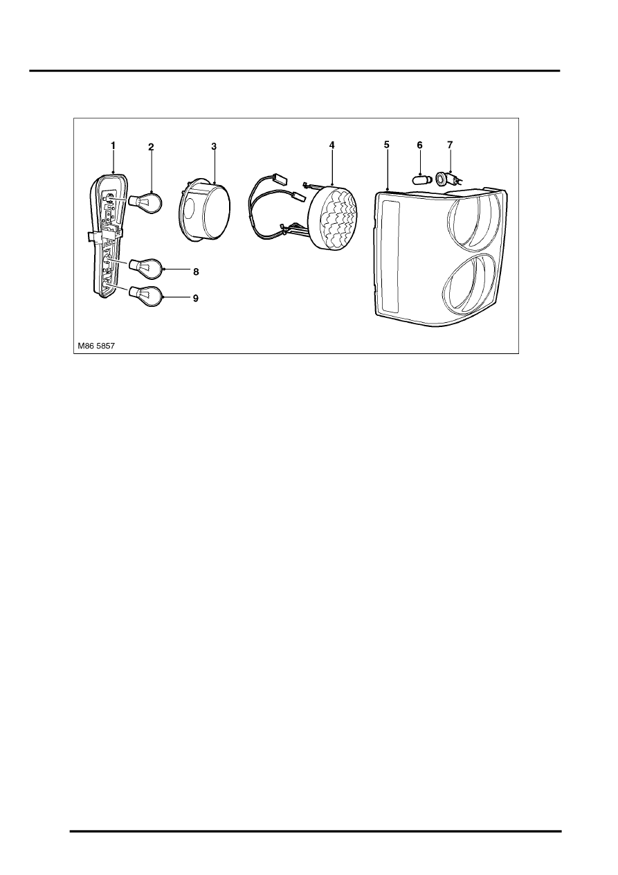
Rear Side and Direction Indicator Lamp Assembly
1 Rear lamp holder
2 Direction indicator bulb
3 Direction indicator reflector
4 Brake lamp LED assembly
5 Tail lamp lens
6 Side marker lamp bulb (NAS only)
7 Side marker lamp bulb holder (NAS only)
8 Bulb – tail lamp twin filament
9 Bulb – tail/rear fog lamp
The rear side and direction indicator lamp assemblies are located on the outer corner of each rear wing panel.
The lamp assembly is retained by two integral plastic clips which locate in corresponding clips secured to the body
panel. The assembly is further retained by two self tapping screws which are accessed from inside the taildoor
aperture. To remove the assembly, after removing the screws, the assembly must be prised at two indentations to
release the clips. A non-metallic tool must be used with care to avoid damage to the paint finish.
The direction indicator, fog lamp and side lamp bulbs are located in a holder. The holders is secured in the lamp
housing by two plastic clips. The holder has a connector to allow for connection to the electrical harness.
The upper lamp aperture is for the brake lamp and the direction indicator. The brake lamp comprises a plastic holder
with contains 19 LED's. This illuminates through a circular prism lens in the centre of the lamp to display the brake
lamp in a red colour. The direction indicator lamp is located behind the brake lamp LED unit. The bulb is located in a
reflector unit which emits the direction indicator light around the outer diameter of the brake lamp LED assembly.
The lower lamp aperture is divided into two parts and provides for the tail lamp and the rear fog lamp The rear fog
lamp uses a 21W bulb in the lower half of the aperture. This is also used for the tail lamp, operated by a PWM output
from the LCM to produce a lower wattage output than the fog lamp. The upper half of the tail lamp aperture is used
solely for the tail lamp and uses a 21W/5W bulb. Only the 5W filament is used for the tail lamp, with the 21W filament
not used by any function.
Parts & tools for this job Staging For Land Rover Range Rover
- PARTReplacement bulbsSearch: Land Rover Range Rover bulbs
- TOOLDigital multimeterSearch: automotive digital multimeter
Links open Amazon search results in a new tab. As an Amazon Associate I earn from qualifying purchases.