
Main Beam/Direction Indicator Column Control Switch
- Make
- Land Rover
- Model
- Range Rover L322 Range Rover System Description and Operation
- Section
- Description › Main Beam/Direction Indicator Column Control Switch
LIGHTING
86-2-24 DESCRIPTION AND OPERATION
Daylight Running Lamps (selected markets only)
In markets which require daylight running lamps, the LCM is programmed with coding which activates the dip beam
or dimmed main beam headlamps when the ignition is in position II.
Daylight running lamps can only be switched on or off using TestBook providing the LCM is not coded with a country
specific code.
Canadian market vehicles use the main beam headlamps with a dimmed output of 5.5 to 6.0V, controlled by the LCM.
Also, on Canadian vehicles with bi-xenon lamps, only the halogen main beam lamp is illuminated using a reduced
voltage of 5.5 to 6.0V. All other countries using daylight running lamps (Finland, Norway and Sweden) use the full
power dip beam headlamps.
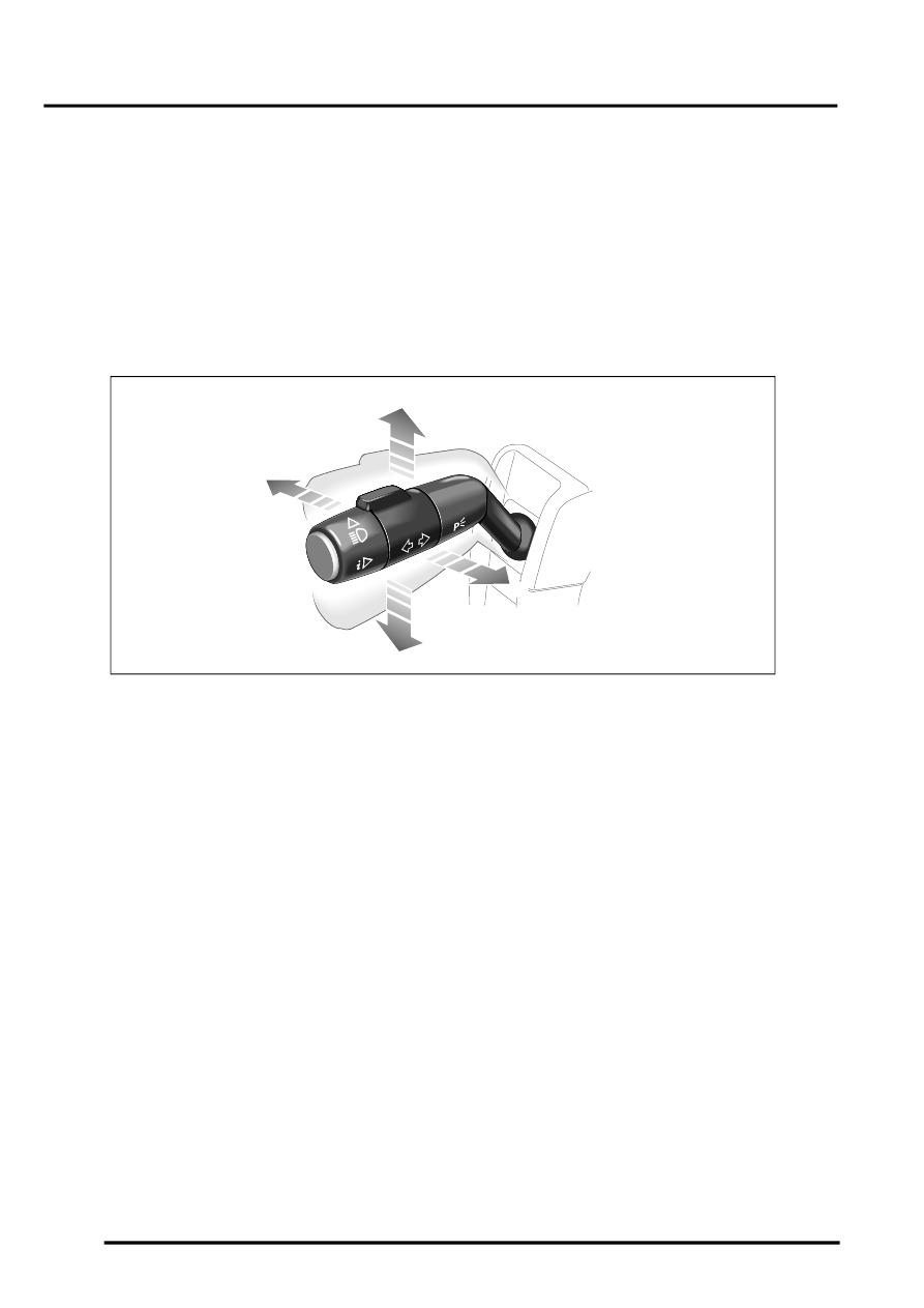
Main Beam/Direction Indicator Column Control Switch
1 RH direction indicator
2 Headlamp flash
3 LH direction indicator
4 Headlamp main beam
The main beam/direction indicator column control switch is located on the left hand side of the steering column and
controls the following functions:
l
Headlamp dip/main beam
l
Headlamp main beam flash
l
Left/right direction indicators
l
Trip computer functions.
INSTRUMENTS, DESCRIPTION AND OPERATION, Description.
The main beam on and flash functions are connected on a single wire to the LCM. The switch assembly contains
resistors and the ground for each selection is passed through a different resistor for each selection. The same also
applies to the direction indicators. The LCM senses the resistance on the ground wire and determines which function
has been selected.
M86 5859
1
2
3
4
Parts & tools for this job Staging For Land Rover Range Rover
- TOOLOBD2 scannerSearch: OBD2 scanner
- TOOLDigital multimeterSearch: automotive digital multimeter
- TOOLBack-probe test leadsSearch: back probe test leads
Links open Amazon search results in a new tab. As an Amazon Associate I earn from qualifying purchases.