
Front Side and Direction Indicator Lamp Assembly
- Make
- Land Rover
- Model
- Range Rover L322 Range Rover System Description and Operation
- Section
- Description › Front Side and Direction Indicator Lamp Assembly
LIGHTING
86-2-20 DESCRIPTION AND OPERATION
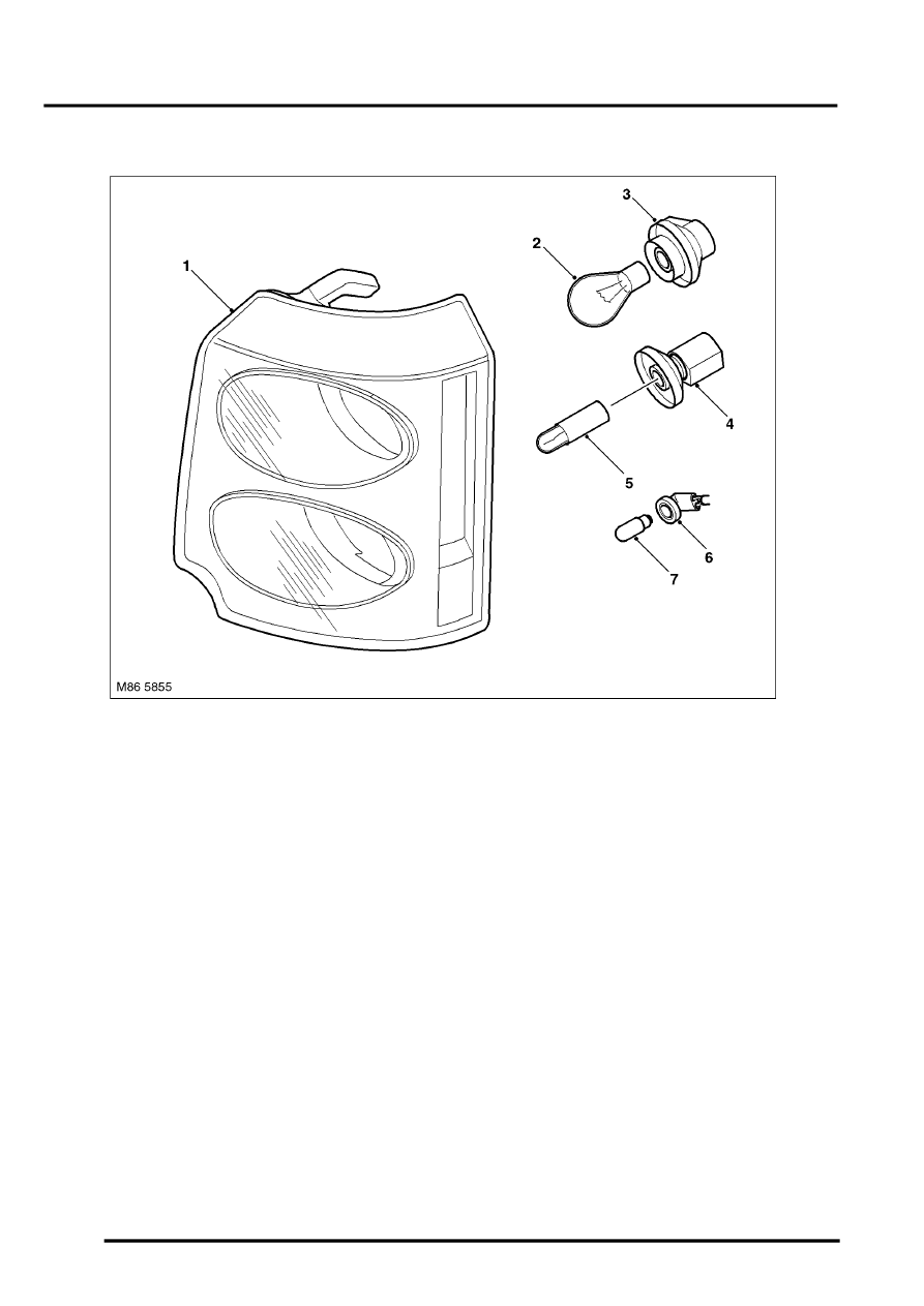
Front Side and Direction Indicator Lamp Assembly
1 Front side and direction indicator lamp
assembly
2 Direction indicator bulb
3 Direction indicator bulb holder
4 Side lamp bulb holder
5 Side lamp bulb
6 Side marker lamp bulb holder (NAS only)
7 Side marker lamp bulb (NAS only)
The front side and direction indicator lamp assemblies are located outboard of each headlamp assembly. The
direction indicator bulbs are 21W bayonet fitting and the side lamp bulbs are 5W bayonet fittings.
The lamp assembly is retained by two integral plastic clips which locate in the headlamp assembly housing. A
threaded shaft locates in a hole in the adjacent wing panel. A knurled nut is and washer is fitted to the threaded shaft
and positively retains the lamp assembly in position. The knurled nut allows for the lamp assembly to be in or out
providing adjustment to ensure flush alignment with the wing contour.
The direction indicator and side lamp bulbs are located in holders. The holders are secured in the lamp housing by
rotating through 90
°
. Each holder has a connector to allow for connection to the electrical harness.
On NAS vehicles, an additional lamp holder is used to accommodate the side marker lamp. The lamp assembly lens
has a vertical section which is used as the side marker illumination required for the NAS market. The side marker lamp
bulb is a 5W bayonet fitting.
Parts & tools for this job Staging For Land Rover Range Rover
- PARTReplacement bulbsSearch: Land Rover Range Rover bulbs
- TOOLDigital multimeterSearch: automotive digital multimeter
Links open Amazon search results in a new tab. As an Amazon Associate I earn from qualifying purchases.