
EAT ECU (page 2 of 2)
- Make
- Land Rover
- Model
- Range Rover L322 Range Rover System Description and Operation
- Section
- Description
AUTOMATIC TRANSMISSION – ZF 5HP24
44-2-44 DESCRIPTION AND OPERATION
Inputs and Outputs
The sensor signals allow the EAT ECU to monitor transmission operation. The ECU processes the incoming signals
and compares this with data stored in its memory. If the received signals are not within the stored values, the ECU
will make adjustments to the transmission operation using the solenoids to provide optimum driveability and
performance.
The sensor inputs provide the EAT ECU with a constant update of the operating condition of the transmission and the
engine. The ECU compares this input data with mapped information stored in its memory and will make any required
adjustments.
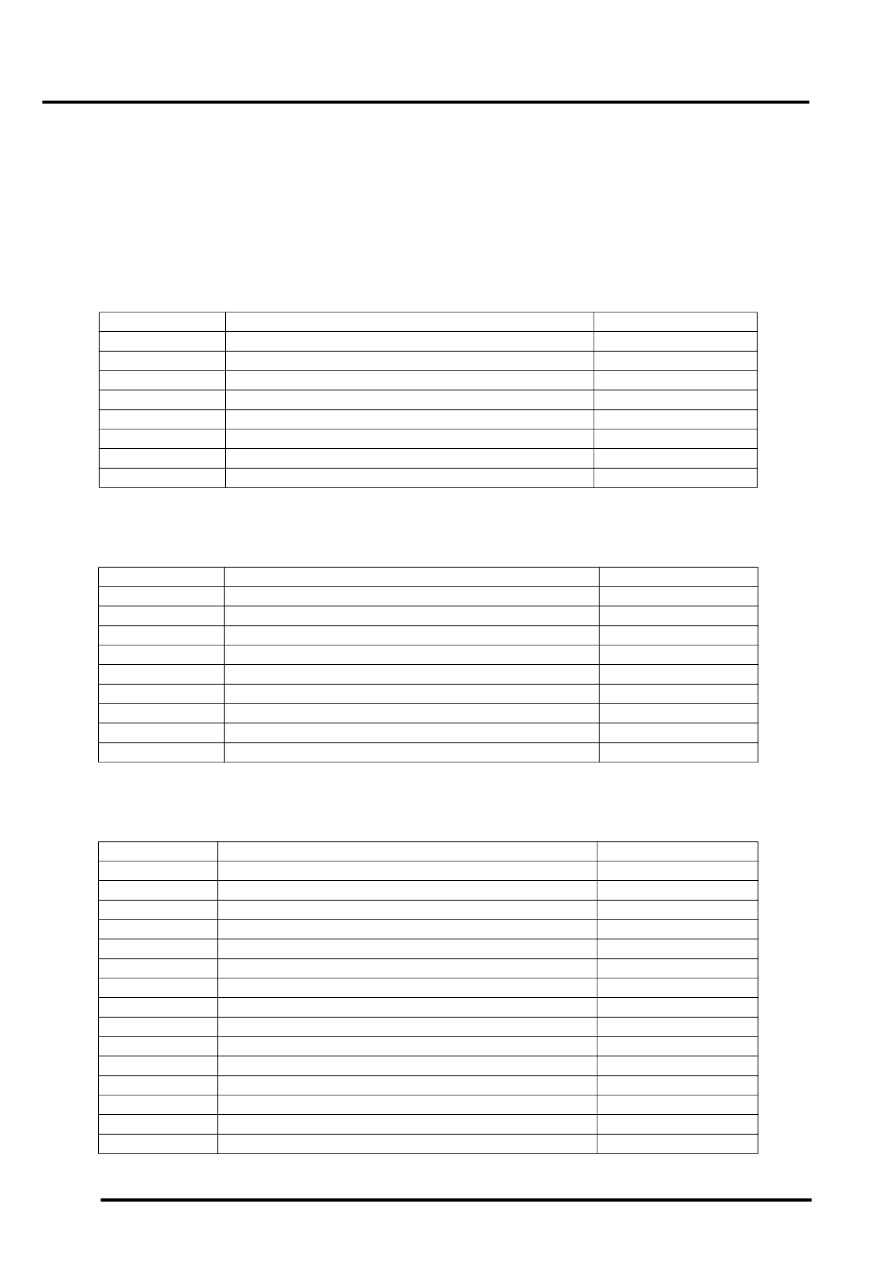
EAT ECU Harness Connector C0193 Pin Details
EAT ECU Harness Connector C0932 Pin Details
EAT ECU Harness Connector C1835 Pin Details
Pin No.
Description
Input/Output
1
Ground for shift interlock solenoid
Input
2
Power supply for shift interlock solenoid
Output
3
Park signal to steering lock ECU
Output
4 to 17
Not used
–
18
HDC switch
Input
19
Selector manual Steptronic switch UP
Input
20
Selector manual Steptronic switch DOWN
Input
21 to 52
Not used
–
Pin No.
Description
Input/Output
1
Ignition power supply
Input
2
Not used
–
3
Diagnostic ISO 9141 K line bus
Input/Output
4
Electronic ground
–
5
Power ground
–
6
Power ground
–
7
Permanent battery power supply
Input
8
Power supply from main relay
Input
9
Power supply from main relay
Input
Pin No.
Description
Input/Output
1
Not used
–
2
Output shaft speed sensor screen
–
3
Output shaft speed sensor signal
Input
4
Inhibitor switch contacts L4
Input
5
Input shaft speed sensor screen
–
6
Ground for EPRS 5
Input
7
Ground for EPRS 4
Input
8 to 10
Not used
–
11
Power supply for EPRS's
Output
12
Temperature sensor supply
Output
13
Output shaft speed sensor supply
Output
14
Inhibitor switch contacts L3
Input
15
Not used
–
16
Ground for SV 3
Input
17
Ground for EPRS 3
Input
Parts & tools for this job Staging For Land Rover Range Rover
- PARTTransmission filter kitSearch: Land Rover Range Rover transmission filter kit
- FLUIDAutomatic transmission fluidSearch: Land Rover automatic transmission fluid
- TOOLFluid transfer pumpSearch: fluid transfer pump
Links open Amazon search results in a new tab. As an Amazon Associate I earn from qualifying purchases.