
LUCAS CONSTANT ENERGY IGNITION SYSTEM - V8i
- Make
- Land Rover
- Model
- Discovery 300Tdi Discovery
- Section
- FAULT DIAGNOSIS › LUCAS CONSTANT ENERGY IGNITION SYSTEM - V8i
86
ELECTRICAL
2
FAULT DIAGNOSIS
LUCAS CONSTANT ENERGY IGNITION SYSTEM -
V8i
Preliminary checks
Inspect battery cables and connections to ensure they
are clean and tight. Check electrical condition of
battery.
Inspect all L.T. connections, ensure they are clean
and tight. Check H.T. leads are correctly positioned
and not shorting to ground against any engine
components. Wiring harness and individual cables
should be firmly fastened to prevent chaffing.
Pick-up air gap
Check air gap between pick-up limb and reluctor teeth
is 0.20 - 0.35 mm, using a non-ferrous gauge.
NOTE: Air gap is set initially at factory and
will only require adjusting if tampered with
or when pick-up module is replaced.
TEST 1:
H.T. Sparking
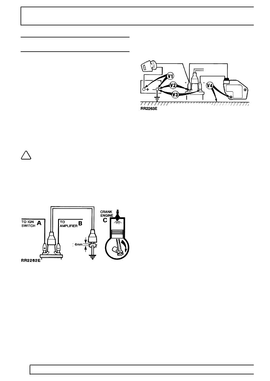
Remove coil/distributor H.T. lead from distributor
cover and hold approximately 6mm from engine block,
using suitable insulated pliers. Switch ignition ’On’ and
operate starter.
Regular sparking indicates fault in H.T. distribution,
plugs, timing or fuelling, proceed to Test 6. If no spark
or weak spark occurs proceed to Test 2.
TEST 2:
L.T. Voltage
Switch ignition ’On’ - engine stationary.
(a)
Connect voltmeter to points in circuit indicated
by V1 to V4 and make a note of voltage
readings.
(b)
Compare voltages obtained with specified
values listed below:
Expected readings
V1
More than 12 volts.
V2
1 volt maximum below volts at V1.
V3
1 volt maximum below volts at V1.
V4
0 volt - 0.1 volt.
(c)
If all readings are correct proceed to Test 3.
(d)
Check incorrect reading(s) with chart to identify
area of possible faults, i.e. faults listed under
heading SUSPECT and rectify.
(e)
If coil and amplifier is suspected, disconnect L.T.
lead at coil, repeat V3. If voltage is still incorrect,
fit new coil. If voltage is now correct, check L.T.
lead, if satisfactory fit new amplifier.
(f)
If engine will not start proceed to Test 3.
Parts & tools for this job Staging For Land Rover Discovery
- PARTSpark plugsSearch: Land Rover Discovery spark plugs
- TOOLSpark plug socketSearch: spark plug socket
- TOOLSpark plug gap toolSearch: spark plug gap tool
Links open Amazon search results in a new tab. As an Amazon Associate I earn from qualifying purchases.