
SERVO ASSEMBLY
- Make
- Land Rover
- Model
- Discovery 300Tdi Discovery
- Section
- REPAIR › SERVO ASSEMBLY
BRAKES
9
REPAIR
SERVO ASSEMBLY
Service repair no - 70.50.01
Remove
Before starting repair refer to general brake service
practice.
See General Brake Service Practice
NOTE: The filter, non-return valve and
grommet, are the only serviceable
components, in event of failure or damage
fit a new unit.
1. Disconnect battery negative lead.
2. Disconnect electrical plug to low fluid level
switch.
3. Thoroughly clean immediate area around all
master cylinder outlet ports. Remove each brake
pipe, sealing each pipe and outlet port to prevent
ingress of foreign matter.
4. Disconnect vacuum supply hose to servo.
5. Remove lower dash panel to gain access to
servo push rod to brake pedal.
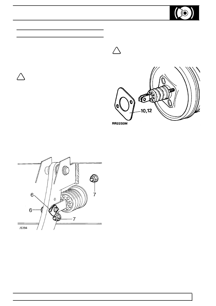
6. Remove clevis pin securing servo push rod to
brake pedal.
7. Remove two nuts and plain washers securing
servo.
8. Remove servo and master cylinder assembly.
9. Drain brake fluid into a suitable container. (If
master cylinder is kept horizontal it is not
necessary to drain fluid).
10. Detach spacer from pedal box mounting face of
servo.
NOTE: Retain spacer for reassembly. The
spacer ensures stringent pedal to servo
operating dimensions are maintained.
11. Remove master cylinder from existing servo and
refit to new servo, if fitting new unit.
Refit
12. Fit spacer to servo.
13. Fit servo to pedal box.
14. Lightly grease brake pedal around area servo
push rod pivots.
15. Fit push rod to lower hole of brake pedal. Fit
clevis pin and clip.
16. Secure servo with two nuts and plain washers.
Tighten nuts to
26 Nm.
17. Refit lower dash panel.
18. Fit master cylinder to servo, refit nuts, plain and
spring washers. Tighten nuts to
26 Nm.
19. Remove all sealing plugs. Refit brake pipes to
respective ports. Tighten brake pipes to
15 Nm.
20. Refit vacuum supply hose.
21. Fill master cylinder to correct level using correct
grade of brake fluid.
See LUBRICANTS,
FLUIDS AND CAPACITIES, Information,
Recommended Lubricants and Fluids
22. Bleed brake system.
Parts & tools for this job Staging For Land Rover Discovery
- PARTBrake padsSearch: Land Rover Discovery brake pads
- TOOLBrake bleeder kitSearch: one man brake bleeder kit
- FLUIDBrake fluidSearch: brake fluid
Links open Amazon search results in a new tab. As an Amazon Associate I earn from qualifying purchases.