
AXLE DIFFERENTIAL ASSEMBLY (page 6 of 7)
- Make
- Land Rover
- Model
- Discovery 300Tdi Discovery
- Section
- OVERHAUL
51
REAR AXLE AND FINAL DRIVE
6
OVERHAUL
48. Repeat on other bearing bore. Add readings
then halve sum to obtain mean reading. Note
whether trace pin has moved up or down from
zero.
A.
Where trace pin moves down, reading is
equal to thickness of shims to remove, to
bring pinion to nominal.
B.
Where trace pin moves up, reading is
equal to thickness of shims to add, to bring
pinion to nominal.
49. Before adjusting shim thickness: check pinion
face marking. If a plus (+) figure, subtract in
thousandths of an inch from shim thickness
figure.
50. If pinion has a minus (-) figure, add amount to
shim thickness figure.
Adjust shim thickness under pinion head bearing
track as necessary.
INCH
MM
.001
=
.025
.002
=
.05
.003
=
.075
.004
=
.10
.005
=
.125
.006
=
.15
.007
=
.175
.008
=
.20
.009
=
.225
.010
=
.25
NOTE: Where dial indicator is metric
conversion must be made to inches when
measuring and selecting shims.
51. Recheck pinion height setting. If setting is
correct, mean reading of dial gauge will agree
with figure marked on pinion end face.
For example, with end face marking of +3, dial
gauge reading should indicate pinion is +0.003
in.
Bearing pre-load adjustment
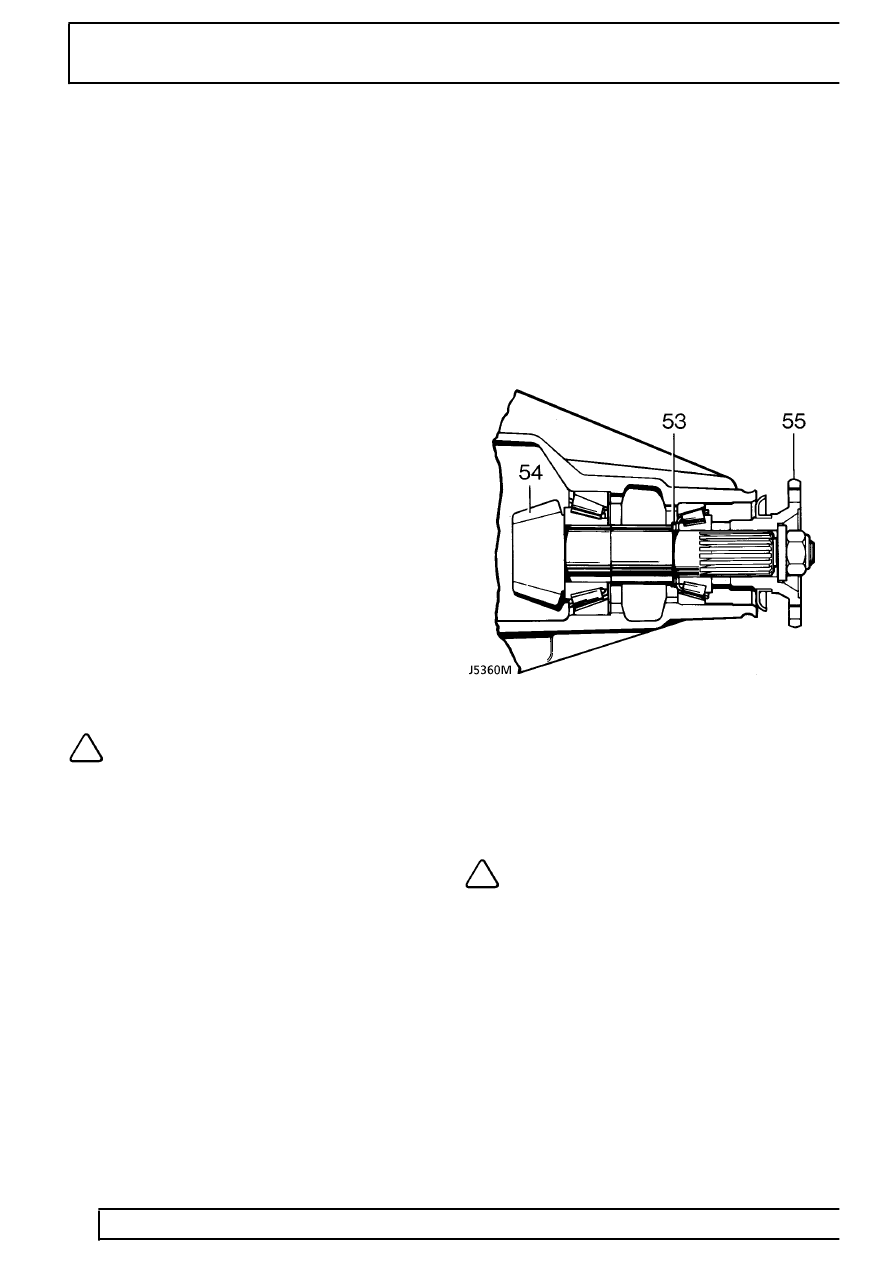
52. Remove the pinion flange, pinion, outer bearing
and spacer.
53. Slide new shim, of same thickness as original
(bearing pre-load) into position on pinion shaft. If
fitting a new shim use thickest shim 2.155 mm.
54. Fit pinion to pinion housing and fit outer bearing
and spacer (front differential only).
55. Fit driving flange, washer and nut.
56. Do not fit oil seal at this stage.
57. Tighten pinion flange nut to
130 Nm. Force to
rotate pinion shaft is 3Nm using new bearings.
Change shim as necessary to obtain reading.
Thicker shim will reduce pre-load. Thinner shim
will increase pre-load.
NOTE: If using original bedded in
bearings, pre-load figure is 1.5 Nm.
58. Remove pinion flange.
Parts & tools for this job Staging For Land Rover Discovery
- PARTRear wheel bearingSearch: Land Rover Discovery rear wheel bearing
- TOOLBearing puller kitSearch: wheel bearing puller kit
- PARTCV boot kitSearch: Land Rover Discovery cv boot kit
Links open Amazon search results in a new tab. As an Amazon Associate I earn from qualifying purchases.