
FRONT PROPELLER SHAFT
- Make
- Land Rover
- Model
- Discovery 300Tdi Discovery
- Section
- REPAIR › FRONT PROPELLER SHAFT
PROPELLER SHAFTS
1
REPAIR
FRONT PROPELLER SHAFT
Service repair no - 47.15.02 - Front
Remove
1. Place vehicle over pit or on a ramp [hoist].
2. Remove nuts from each end of propeller shaft.
Remove shaft.
3. Scribe alignment marks on flanges at both ends
of propeller shaft to ensure correct refitting.
Service repair no - 47.15.11
Overhaul
4. Thoroughly examine universal joint for signs of
damage or wear. Replace if necessary.
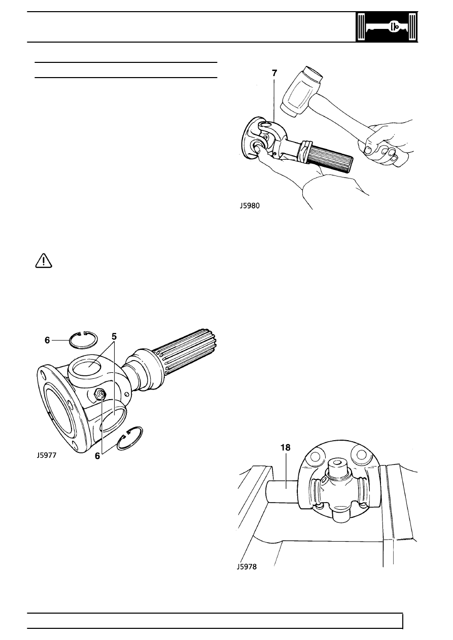
5. Clean universal joint bearing cups and circlips.
CAUTION: To ensure correct assembly
and reduce possibility of imbalance.
Before removing propeller shaft joint. Mark
position of spider pin lubricator relative to journal
yoke ears.
6. Remove circlips, and grease nipple.
7. Tap yokes to eject bearing cups.
8. Remove bearing cups and spider.
9. Repeat instructions 4 to 7 for opposite end of
propeller shaft if necessary.
10. Clean yokes and bearing cup locations.
Assemble
11. Remove bearing cups from new spider.
12. Check all needle rollers are present and
positioned in bearing cups.
13. Ensure bearing cups are one-third full of
lubricant.
See LUBRICANTS, FLUIDS AND
CAPACITIES, Information, Recommended
Lubricants and Fluids
14. Enter new spider with seals into yokes of sliding
member flange.
15. Partially insert one bearing cup into flange yoke
and enter spider trunnion into bearing cup.
16. Insert opposite bearing cup into flange yoke.
17. Press both cups into place.
Parts & tools for this job Staging For Land Rover Discovery
- TOOLTorque wrenchSearch: 3/8 inch torque wrench
- TOOLSocket setSearch: socket set metric
- BOOKHaynes manualSearch: Haynes manual Land Rover Discovery
Links open Amazon search results in a new tab. As an Amazon Associate I earn from qualifying purchases.