
Timing system protective COVER(S) - R.R.
- Make
- Lancia
- Model
- Thesis Factory Service Manual
- Year
- 2002–2009
- Section
- Timing system › Timing system protective COVER(S) - R.R.
Timing system protective COVER(S) - R.R.
Removing
- Position the vehicle on a lift.
- Open the boot and disconnect the negative battery terminal.
See in Op. 7055B54 PROTECTION/GUARD under engine - R.R.
See in Op. 4450B04 Right FRONT WHEEL (one) - R.R.
See in Op. 7055B42 FRONT WHEEL ARCH LINER (one), left or right - R.R.
See in Op. 7055B64 Engine compartment DUST SEAL in front wheel arch (one), left or right - R.R.
See in Op. 1016A10 SOUND-PROOFING COVER - R.R.
See in Op. 7040D50 ENGINE COMPARTMENT UPPER SOUND INSULATION SHIELD - R.R.
See in Op. 1048B44 RIGID air supply PIPE from heat exchanger to intake manifold - R.R.
See in Op. 1048A56 UPPER RESONATOR - R.R.
See in Op. 1092G10 Engine components single drive BELT - R.R.
See in Op. 1092G21 Engine components single belt FIXED TENSIONER - R.R. with belt removed
See in Op. 1092A10 Crankshaft PULLEY - R.R.
1. Disconnect the electrical connection for the engine coolant level sensor.
| Description | Connector | |
|---|---|---|
| 1 | Engine coolant level sensor | K026 |
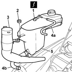
2. Undo the nut fixing the engine coolant reservoir and the screen washer fluid filler pipe.
3. Remove the windscreen washer fluid filler pipe.
- Position a suitable container for collecting the engine coolant.
4. Disconnect the flexible engine coolant recirculation pipes from the reservoir (4a) and the flexible pipe from the rigid pipe (4b).
5. Remove the engine coolant reservoir.
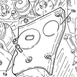
1. Undo the retaining bolts.
2. Remove the lower section of the timing protective cover.
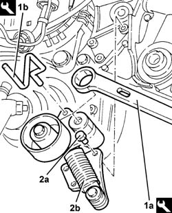
1. Remove the pin (1b) using the tool (1a) on the moving tensioner.
| Description | Code | Function | |
|---|---|---|---|
| 1a | Spanner | 1.860.968.000 | Tensioning auxiliary shaft belt |
| Description | Code | Function | |
|---|---|---|---|
| 1b | Lock | 1.870.645.000 | Tensioning auxiliary shaft belt |
2. Undo the fixing bolt (2a) and remove the services belt moving tensioner (2b).
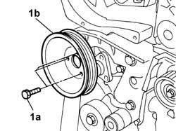
1. Undo the fixing bolts (1a) and remove the power assisted steering pump pulley (1b).
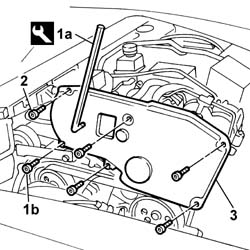
1. Undo the fixing bolt (1b) using the special hexagonal spanner (1a).
| Description | Code | Function | |
|---|---|---|---|
| 1a | Spanner | 1.871.001.100 | Spanner for timing guard |
2. Undo the remaining fixing bolts using an ordinary spanner.
3. Remove the timing belt upper cover.
Refitting
- Fit the upper part of the protective cover and tighten the fixing bolts to the recommended torque and tighten the remaining fixing bolts using the special tool.
| Description | Code | Function | |
|---|---|---|---|
| Spanner | 1.871.001.100 | Spanner for timing guard |
| Value - daNm | Fastening | Component | Ø | |
|---|---|---|---|---|
| 0.9 | Bolt | TIMING BELT PROTECTIVE COVER(S) | M6 |
- Fit the power assisted steering pump pulley in the housing on the support.
- Tighten the bolts fixing thepower assisted steering pump to the support to torque.
| Value - daNm | Fastening | Component | Ø | |
|---|---|---|---|---|
| 2.5 | Bolt | POWER STEERING PUMP | M8 |
1. Fit the auxiliary shaft drive belt moving tensioner.
2. Tighten the fixing bolts to torque.
| Value - daNm | Fastening | Component | Ø | |
|---|---|---|---|---|
| 2 | 2.5 | Bolts | SINGLE BELT MOVING TENSIONER VARIOUS | M8 |
| Value - daNm | Fastening | Component | Ø | |
|---|---|---|---|---|
| 2 | 6 | Bolts | SINGLE BELT MOVING TENSIONER VARIOUS | M10 |
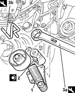
3. Fit the moving tensioner spring pre-loading pin (3b) acting on the moving tensioner using the tool (3b).
| Description | Code | Function | |
|---|---|---|---|
| 3a | Spanner | 1.860.968.000 | Tensioning auxiliary shaft belt |
| Description | Code | Function | |
|---|---|---|---|
| 3b | Lock | 1.870.645.000 | Tensioning auxiliary shaft belt |
- Fit the lower section of the protective cover tightening the fixing bolts to torque.
| Value - daNm | Fastening | Component | Ø | |
|---|---|---|---|---|
| 0.9 | Bolt | TIMING BELT PROTECTIVE COVER(S) | M6 |
- Connect the engine coolant pipes to the reservoir.
- Position the engine coolant reservoir in the special housing together with the screen washer fluid filler pipe.
- Tighten the engine coolant reservoir fixing nut.
- Connect the electrical connection for the engine coolant level sensor.
| Description | Connector | |
|---|---|---|
| Engine coolant level sensor | K026 |
See in Op. 1092A10 Crankshaft PULLEY - R.R.
See in Op. 1092G21 Engine components single belt FIXED TENSIONER - R.R. with belt removed
See in Op. 1092G10 Engine components single drive BELT - R.R.
See in Op. 1048A56 UPPER RESONATOR - R.R.
See in Op. 1048B44 RIGID air supply PIPE from heat exchanger to intake manifold - R.R.
See in Op. 7040D50 ENGINE COMPARTMENT UPPER SOUND INSULATION SHIELD - R.R.
See in Op. 1016A10 SOUND-PROOFING COVER - R.R.
See in Op. 7055B64 Engine compartment DUST SEAL in front wheel arch (one), left or right - R.R.
See in Op. 7055B42 FRONT WHEEL ARCH LINER (one), left or right - R.R.
See in Op. 7055B54 PROTECTION/GUARD under engine - R.R.
See in Op. 4450B04 Right FRONT WHEEL (one) - R.R.
- Top up the engine coolant, following the instructions in the description:
See in Op. 0010T21 ENGINE COOLANT - Check density and top up if necessary
- Connect the negative battery terminal.
- Remove the vehicle from the lift.
Removing
- Position the vehicle on a lift.
- Open the boot and disconnect the negative battery terminal.
See in Op. 7040D50 ENGINE COMPARTMENT UPPER SOUND INSULATION SHIELD - R.R.
See in Op. 1016A10 SOUND-PROOFING COVER - R.R.
See in Op. 7055B54 PROTECTION/GUARD under engine - R.R.
See in Op. 4450B04 Right FRONT WHEEL (one) - R.R.
See in Op. 7055B42 FRONT WHEEL ARCH LINER (one), left or right - R.R.
See in Op. 7055B64 Engine compartment DUST SEAL in front wheel arch (one), left or right - R.R.
See in Op. 1092G10 Engine components single drive BELT - R.R.
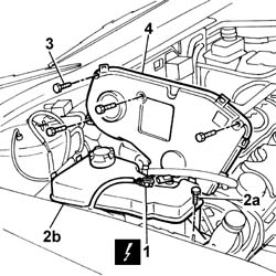
1. Disconnect the electrical connection for the engine coolant level sensor.
| Description | Connector | |
|---|---|---|
| 1 | Engine coolant level sensor | K026 |
2. Undo the fixing bolt (2a) and move the engine coolant reservoir (2b) from the housing.
3. Undo the fixing bolts.
3. Remove the upper timing protective cover.
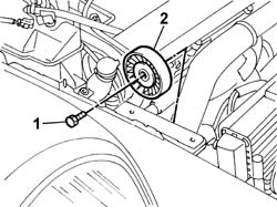
1. Undo the fixing bolt.
2. Remove the auxiliary shaft drive belt fixed tensioner.
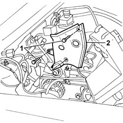
1. Undo the lower fixing bolts.
2. Remove the lower section of the timing protective cover.
Refitting
- Fit the lower section of the protective cover and tighten the fixing bolts to the recommended torque.
| Value - daNm | Fastening | Component | Ø | |
|---|---|---|---|---|
| 0.9 | Bolt | TIMING BELT PROTECTIVE COVER(S) | M6 |
- Fit the auxiliary shaft drive belt fixed tensioner and tighten the retaining bolt to torque.
| Value - daNm | Fastening | Component | Ø | |
|---|---|---|---|---|
| 2.5 | Bolt | SINGLE BELT FIXED TENSIONER VARIOUS | M8 |
- Fit the upper section of the protective cover tightening the fixing bolts to torque.
| Value - daNm | Fastening | Component | Ø | |
|---|---|---|---|---|
| 0.9 | Bolt | TIMING BELT PROTECTIVE COVER(S) | M6 |
- Place the engine coolant reservoir in position and tighten the fixing bolt.
- Connect the electrical connection for the engine coolant level sensor.
| Description | Connector | |
|---|---|---|
| Engine coolant level sensor | K026 |
See in Op. 1092G10 Engine components single drive BELT - R.R.
See in Op. 7055B64 Engine compartment DUST SEAL in front wheel arch (one), left or right - R.R.
See in Op. 7055A42 FRONT GRILLE (single) - R.R.
See in Op. 4450B04 Right FRONT WHEEL (one) - R.R.
See in Op. 7055B54 PROTECTION/GUARD under engine - R.R.
See in Op. 1016A10 SOUND-PROOFING COVER - R.R.
See in Op. 7040D50 ENGINE COMPARTMENT UPPER SOUND INSULATION SHIELD - R.R.
- Open the boot and connect the negative battery terminal.
- Remove the vehicle from the lift.
Removing
- Position the vehicle on a lift.
- Open the boot, remove the cover on the left hand side and disconnect the negative battery lead.
- Position a suitable container for collecting the engine coolant.
- Raise the lift.
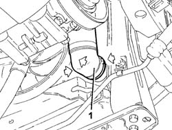
1. Disconnect the lower radiator pipe.
See in Op. 7040D50 ENGINE COMPARTMENT UPPER SOUND INSULATION SHIELD - R.R.
See in Op. 4450B04 Right FRONT WHEEL (one) - R.R.
- Raise the vehicle on the lift.
See in Op. 7055B54 PROTECTION/GUARD under engine - R.R.
See in Op. 7055B42 FRONT WHEEL ARCH LINER (one), left or right - R.R.
See in Op. 7055B64 Engine compartment DUST SEAL in front wheel arch (one), left or right - R.R.
See in Op. 1048A28 vacuum air circuit resonator pipe - r+r
See in Op. 1048A21 AIR INLET HOSE FROM INTAKE TO FILTER - R.R.
See in Op. 1048A10 COMPLETE AIR FILTER -R.R.
See in Op. 1016A40 Ignition COIL COVER on cylinder head - R.R.
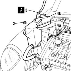
1. Disconnect the coolant pipe retaining band on the cylinder head.
2. Undo the nut fixing the expansion tank (this nut also fastens the windscreen washer fluid reservoir).
3. Disconnect the electrical connection for the engine coolant level.
| Description | Connector | |
|---|---|---|
| 3 | Engine coolant level sensor | K026 |
4. Disconnect the pipe (4a) and raise the expansion tank (4b) and remove it.
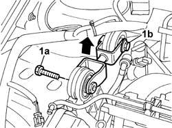
1. Undo the bolt (1a), loosen the bolt (1b) and rotate the reaction rod connecting rod.
- Raise the vehicle on the lift.
1. Undo the nuts fixing the catalytic converter to the centre section of the exhaust pipe.
2. Remove the mounting bracket for the front section of the exhaust pipe.
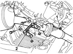
- Lower the vehicle on the lift, then position a hydraulic lift under the bellhousing.
1. Undo the bolts fixing the engine support to the gearbox.
- Gradually lower the hydraulic lift and rest the gearbox on the front crossmember.
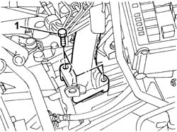
See in Op. 1092G10 Engine components single drive BELT - R.R.
See in Op. 1092A10 Crankshaft PULLEY - R.R. for versions with air conditioner
1. Undo the bolt fixing the auxiliary shaft drive belt idle pulley.
2. Undo the five bolts (2a) and remove the timing drive belt protective cover (2b).
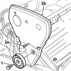
Refitting
- Position the timing drive belt cover and secure it using the fixing bolts.
| Value - daNm | Fastening | Component | Ø | |
|---|---|---|---|---|
| 0.9 | Bolt | TIMING BELT PROTECTIVE COVER(S) | M6 |
- Tighten the bolt fixing the auxiliary shaft drive belt idle pulley.
See in Op. 1092A10 Crankshaft PULLEY - R.R. for versions with air conditioner
See in Op. 1092G10 Engine components single drive BELT - R.R.
- Position a hydraulic lift under the gearbox bellhousing.
- Screw in and tighten the bolt fixing the engine support to the gearbox to the recommended torque.
| Value - daNm | Fastening | Component | Ø | |
|---|---|---|---|---|
| 5 | Bolt | POWER UNIT GEAR BOX END RIGID MOUNT | M10 X 1.25 |
- Raise the vehicle on the lift.
- Tighten the nuts fixing the catalytic converter to the centre section of the exhaust pipe.
| Value - daNm | Fastening | Component | Ø | |
|---|---|---|---|---|
| (to cable centre section) 2.8 | Nut | CATALYTIC CONVERTER (ONE) | M8 |
- Fit the mounting bracket for the front section of the exhaust pipe.
| Value - daNm | Fastening | Component | Ø | |
|---|---|---|---|---|
| (on engine oil sump) 4 | Nut | CATALYTIC CONVERTER MOUNT | M10 X 1.25 |
| Value - daNm | Fastening | Component | Ø | |
|---|---|---|---|---|
| (to catalytic converter) 2.8 | Bolt | CATALYTIC CONVERTER MOUNT | M8 |
- Lower the vehicle on the lift.
- Connect the connecting rod to the reaction rod and secure it using the bolts.
| Value - daNm | Fastening | Component | Ø | |
|---|---|---|---|---|
| (to bracket on bodyshell) 5 | Bolt | POWER UNIT REACTION ROD | M10 X 1.25 |
| Value - daNm | Fastening | Component | Ø | |
|---|---|---|---|---|
| (to engine support) 5 | Bolt | POWER UNIT REACTION ROD | M10 X 1.25 |
- Position the expansion tank and secure it using the nut.
- Connect the pipes and the electrical connection for the engine coolant level.
| Description | Connector | |
|---|---|---|
| Engine coolant level sensor | K026 |
See in Op. 1048A10 COMPLETE AIR FILTER -R.R.
See in Op. 1048A21 AIR INLET HOSE FROM INTAKE TO FILTER - R.R.
See in Op. 1048A28 vacuum air circuit resonator pipe - r+r
See in Op. 1016A40 Ignition COIL COVER on cylinder head - R.R.
See in Op. 7055B64 Engine compartment DUST SEAL in front wheel arch (one), left or right - R.R.
See in Op. 7055B42 FRONT WHEEL ARCH LINER (one), left or right - R.R.
- Connect the lower radiator pipe.
- Lower the vehicle on the lift.
See in Op. 4450B04 Right FRONT WHEEL (one) - R.R.
- Connect the negative battery lead.
See in Op. 0010T20 Engine REFRIGERANT FLUID - Change
See in Op. 7055B54 PROTECTION/GUARD under engine - R.R.
See in Op. 7040D50 ENGINE COMPARTMENT UPPER SOUND INSULATION SHIELD - R.R.
- Remove the vehicle from the lift.
Removing
- Position the vehicle on a lift.
- Open the boot, remove the cover on the left hand side and disconnect the negative battery lead.
See in Op. 4450B04 Right FRONT WHEEL (one) - R.R.
- Raise the vehicle on the lift.
See in Op. 7055B54 PROTECTION/GUARD under engine - R.R.
See in Op. 7055B64 Engine compartment DUST SEAL in front wheel arch (one), left or right - R.R.
See in Op. 7055B42 FRONT WHEEL ARCH LINER (one), left or right - R.R.
See in Op. 1092G10 Engine components single drive BELT - R.R.
- Lower the lift.
See in Op. 7040D50 ENGINE COMPARTMENT UPPER SOUND INSULATION SHIELD - R.R.
See in Op. 1088B10 Engine coolant SUPPLY RESERVOIR - R.R.
See in Op. 1048A21 AIR INLET HOSE FROM INTAKE TO FILTER - R.R.
See in Op. 1048A28 vacuum air circuit resonator pipe - r+r
See in Op. 1008C10 Power unit REACTION ROD - Replace
See in Op. 1016A42 LEFT CYLINDER HEAD IGNITION COIL COVER - R.R.
See in Op. 1048A11 COMPLETE AIR FILTER -R.R.
1. Release the retainers (1a) and disconnect the gearbox bowden cable (1b).
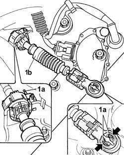
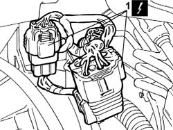
1. Disconnect the main gearbox wiring connectors.
| Description | Connector | |
|---|---|---|
| 1 | Automatic transmission solenoid valves | L050A |
| Description | Connector | |
|---|---|---|
| 1 | Automatic transmission solenoid valves | L050B |
| Description | Connector | |
|---|---|---|
| 1 | Automatic transmission solenoid valves | L050C |
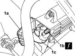
1. Open the protective flap (1a) and undo the nut (1b) fixing the starter motor supply lead (1c) to the junction node and move the lead between the junction node and the motor aside.
| Description | Connector | |
|---|---|---|
| 1b | Contact board | A005A |
| Description | Connector | |
|---|---|---|
| 1b | Contact board | A005B |
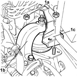
1. Position a hydraulic jack under the gearbox casing and undo the two nuts (1a) fixing the gearbox side engine support (1b) to the bracket (1c), then lower the jack until the gearbox casing is resting on the suspension frame.
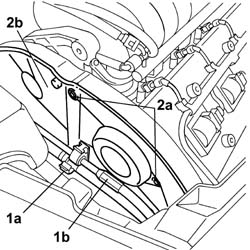
1. Open the band (1a) retaining the power assisted steering pipes (1b) and move them aside.
2. Undo the six upper bolts (2a) fixing the timing belt upper cover (2b) and remove it.
Refitting
- Position the timing belt upper cover and tighten the fixing bolts.
| Value - daNm | Fastening | Component | Ø | |
|---|---|---|---|---|
| 0.9 | Bolt | TIMING BELT PROTECTIVE COVER(S) | M6 |
- Position the power assisted steering pipes and close the retaining band.
- Raise the jack positioned under the gearbox casing and tighten the two nuts fixing the gearbox side engine support to the bracket to the recommended torque.
| Value - daNm | Fastening | Component | Ø | |
|---|---|---|---|---|
| 5 | Nut | POWER UNIT GEAR BOX END RIGID MOUNT | M10 X 1.25 |
- Connect the lead between the junction node and the starter motor to the actual node and tighten the fixing nut, then close the protective flap.
| Value - daNm | Fastening | Component | Ø | |
|---|---|---|---|---|
| 0.5 | Nut | TERMINAL/MOTOR LEAD | M8 |
- Connect the main gearbox wiring connectors.
| Description | Connector | |
|---|---|---|
| Automatic transmission solenoid valves | L050A |
| Description | Connector | |
|---|---|---|
| Automatic transmission solenoid valves | L050B |
| Description | Connector | |
|---|---|---|
| Automatic transmission solenoid valves | L050C |
- Position the gearbox bowden cable and secure the retainers.
See in Op. 1048A11 COMPLETE AIR FILTER -R.R.
See in Op. 1016A42 LEFT CYLINDER HEAD IGNITION COIL COVER - R.R.
See in Op. 1008C10 Power unit REACTION ROD - Replace
See in Op. 1048A28 vacuum air circuit resonator pipe - r+r
See in Op. 1048A21 AIR INLET HOSE FROM INTAKE TO FILTER - R.R.
See in Op. 1088B10 Engine coolant SUPPLY RESERVOIR - R.R.
See in Op. 7040D50 ENGINE COMPARTMENT UPPER SOUND INSULATION SHIELD - R.R.
- Raise the vehicle.
See in Op. 1092G10 Engine components single drive BELT - R.R.
See in Op. 7055B64 Engine compartment DUST SEAL in front wheel arch (one), left or right - R.R.
See in Op. 4450B04 Right FRONT WHEEL (one) - R.R.
- Raise the vehicle on the lift.
- Connect the negative battery lead, then close the boot.
- Remove the vehicle from the lift.
See in Op. 0010T21 ENGINE COOLANT - Check density and top up if necessary
Removing
- Position the vehicle on a lift.
- Open the boot, remove the cover on the left hand side and disconnect the negative battery lead.
- Position a suitable container for collecting the engine coolant.
- Raise the lift.
1. Disconnect the lower radiator pipe.
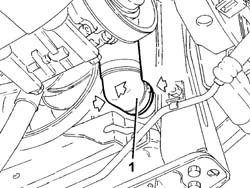
See in Op. 7040D50 ENGINE COMPARTMENT UPPER SOUND INSULATION SHIELD - R.R.
See in Op. 4450B04 Right FRONT WHEEL (one) - R.R.
- Raise the vehicle on the lift.
See in Op. 7055B54 PROTECTION/GUARD under engine - R.R.
See in Op. 7055B42 FRONT WHEEL ARCH LINER (one), left or right - R.R.
See in Op. 7055B64 Engine compartment DUST SEAL in front wheel arch (one), left or right - R.R.
See in Op. 1048A21 AIR INLET HOSE FROM INTAKE TO FILTER - R.R.
See in Op. 1048A50 air inlet pipe to turbocharger - r + r
See in Op. 1048A10 COMPLETE AIR FILTER -R.R.
See in Op. 1016A40 Ignition COIL COVER on cylinder head - R.R.
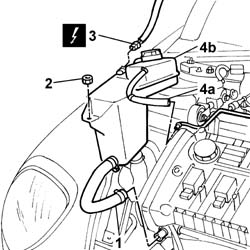
1. Disconnect the coolant pipe retaining band on the cylinder head.
2. Undo the nut fixing the expansion tank (this nut also fastens the windscreen washer fluid reservoir).
3. Disconnect the electrical connection for the engine coolant level.
| Description | Connector | |
|---|---|---|
| 3 | Engine coolant level sensor | K026 |
4. Disconnect the pipe (4a) and raise the expansion tank (4b) and remove it.
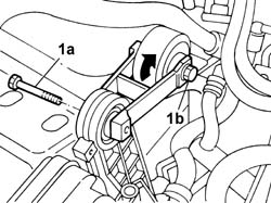
1. Undo the bolt (1a), loosen the bolt (1b) and rotate the reaction rod connecting rod.
- Raise the vehicle on the lift.
1. Undo the nuts fixing the catalytic converter to the centre section of the exhaust pipe.
2. Remove the mounting bracket for the front section of the exhaust pipe.
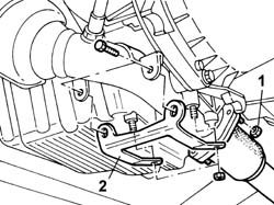
- Lower the vehicle on the lift, then position a hydraulic lift under the bellhousing.
1. Undo the bolts fixing the engine support to the gearbox.
- Gradually lower the hydraulic lift and rest the gearbox on the front crossmember.
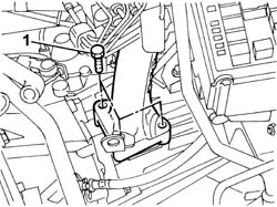
See in Op. 1092G10 Engine components single drive BELT - R.R.
See in Op. 1092A10 Crankshaft PULLEY - R.R. for versions with air conditioner
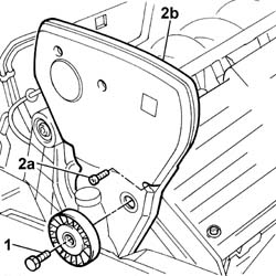
1. Undo the bolt fixing the auxiliary shaft drive belt idle pulley.
2. Undo the five bolts (2a) and remove the timing drive belt protective cover (2b).
Refitting
- Position the timing drive belt cover and secure it using the fixing bolts.
| Value - daNm | Fastening | Component | Ø | |
|---|---|---|---|---|
| 0.9 | Bolt | TIMING BELT PROTECTIVE COVER(S) | M6 |
- Tighten the bolt fixing the auxiliary shaft drive belt idle pulley.
See in Op. 1092A10 Crankshaft PULLEY - R.R. for versions with air conditioner
See in Op. 1092G10 Engine components single drive BELT - R.R.
- Position a hydraulic lift under the gearbox bellhousing.
- Screw in and tighten the bolt fixing the engine support to the gearbox to the recommended torque.
| Value - daNm | Fastening | Component | Ø | |
|---|---|---|---|---|
| 5 | Bolt | POWER UNIT GEAR BOX END RIGID MOUNT | M10 X 1.25 |
- Raise the vehicle on the lift.
- Tighten the nuts fixing the catalytic converter to the centre section of the exhaust pipe.
| Value - daNm | Fastening | Component | Ø | |
|---|---|---|---|---|
| (to cable centre section) 2.8 | Nut | CATALYTIC CONVERTER (ONE) | M8 |
- Fit the mounting bracket for the front section of the exhaust pipe.
| Value - daNm | Fastening | Component | Ø | |
|---|---|---|---|---|
| (on engine oil sump) 4 | Nut | CATALYTIC CONVERTER MOUNT | M10 X 1.25 |
| Value - daNm | Fastening | Component | Ø | |
|---|---|---|---|---|
| (to catalytic converter) 2.8 | Bolt | CATALYTIC CONVERTER MOUNT | M8 |
- Lower the vehicle on the lift.
- Connect the connecting rod to the reaction rod and secure it using the bolts.
| Value - daNm | Fastening | Component | Ø | |
|---|---|---|---|---|
| (to bracket on bodyshell) 5 | Bolt | POWER UNIT REACTION ROD | M10 X 1.25 |
| Value - daNm | Fastening | Component | Ø | |
|---|---|---|---|---|
| (to engine support) 5 | Bolt | POWER UNIT REACTION ROD | M10 X 1.25 |
- Position the expansion tank and secure it using the nut.
- Connect the pipes and the electrical connection for the engine coolant level.
| Description | Connector | |
|---|---|---|
| Engine coolant level sensor | K026 |
See in Op. 1016A40 Ignition COIL COVER on cylinder head - R.R.
See in Op. 1048A10 COMPLETE AIR FILTER -R.R.
See in Op. 1048A50 air inlet pipe to turbocharger - r + r
See in Op. 1048A21 AIR INLET HOSE FROM INTAKE TO FILTER - R.R.
See in Op. 1016A40 Ignition COIL COVER on cylinder head - R.R.
See in Op. 7055B64 Engine compartment DUST SEAL in front wheel arch (one), left or right - R.R.
See in Op. 7055B42 FRONT WHEEL ARCH LINER (one), left or right - R.R.
- Connect the lower radiator pipe.
- Lower the vehicle on the lift.
See in Op. 4450B04 Right FRONT WHEEL (one) - R.R.
- Connect the negative battery lead.
See in Op. 0010T20 Engine REFRIGERANT FLUID - Change
See in Op. 7055B54 PROTECTION/GUARD under engine - R.R.
See in Op. 7040D50 ENGINE COMPARTMENT UPPER SOUND INSULATION SHIELD - R.R.
- Remove the vehicle from the lift.
Parts & tools for this job Staging For 2002 Lancia Thesis
- PARTEngine gasket setSearch: Lancia Thesis 2002 engine gasket set
- TOOLTorque wrenchSearch: 3/8 inch torque wrench
- TOOLFeeler gauge setSearch: feeler gauge set
Links open Amazon search results in a new tab. As an Amazon Associate I earn from qualifying purchases.