
Engine components single drive BELT - R.R.
- Make
- Lancia
- Model
- Thesis Factory Service Manual
- Year
- 2002–2009
- Section
- Engine component miscellaneous drives › Engine components single drive BELT - R.R.
Engine components single drive BELT - R.R.
Removing
- Position the vehicle on a lift.
- Open the boot and disconnect the negative battery terminal.
See in Op. 7055B54 PROTECTION/GUARD under engine - R.R.
See in Op. 4450B04 Right FRONT WHEEL (one) - R.R.
See in Op. 7055B42 FRONT WHEEL ARCH LINER (one), left or right - R.R.
See in Op. 7055B64 Engine compartment DUST SEAL in front wheel arch (one), left or right - R.R.
See in Op. 1016A10 SOUND-PROOFING COVER - R.R.
See in Op. 7040D50 ENGINE COMPARTMENT UPPER SOUND INSULATION SHIELD - R.R.
See in Op. 1048B44 RIGID air supply PIPE from heat exchanger to intake manifold - R.R.
See in Op. 1048A56 UPPER RESONATOR - R.R.
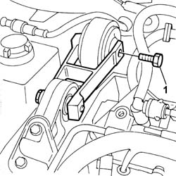
1. Undo the bolt fixing the reaction rod to the bodyshell.
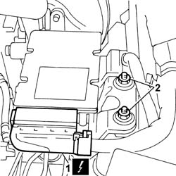
1. Remove the safety sealant applied to the electrical connector, then disconnect the braking system control unit electrical connector (NFR).
| Description | Connector | |
|---|---|---|
| 1 | Braking system control unit (NFR) | M051 |
2. Undo the nuts securing the braking system control unit (NFR) to the mounting bracket.
- Position a hydraulic lift under the gearbox to support the power unit.
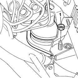
1. Undo the nuts securing the flexible mounting to the mounting bracket.
- Gently lower the hydraulic lift until the bellhousing is resting on the crossmember.
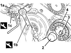
1. Adjust the moving tensioner (1a) for the single drive belt using the spanner (1b), then insert the tool (1c) in the opening in the tensioner.
| Description | Code | Function | |
|---|---|---|---|
| 1b | Spanner | 1.860.966.000 | Tensioning auxiliary shaft belt |
| Description | Code | Function | |
|---|---|---|---|
| 1c | Lock | 1.870.645.000 | Tensioning auxiliary shaft belt |
2. Remove the protective plug for the auxiliar shaft drive belt cam tensioner.
3. Undo the bolt retaining the cam tensioner.
4. Remove the auxiliary shaft drive belt.
Refitting
- Fit the single drive belt on the pullies.
Avoid the belt coming into contact with oil or solvents that could alter the flexibility of the rubber with a resulting loss of adhesion. Also check that the belt shows no signs of cracks or cuts or else it will have to be played.
1. Rotate the cam tensioner (1a) using the tool (1b) until the clip (1c) can be released easily, then lock the bolt (1d) fixing the cam tensioner.
| Description | Code | Function | |
|---|---|---|---|
| 1b | Spanner | 1.860.968.000 | Tensioning auxiliary shaft belt |
| Description | Code | Function | |
|---|---|---|---|
| Lock | 1.870.645.000 | Tensioning auxiliary shaft belt |
| Value - daNm | Fastening | Component | Ø | |
|---|---|---|---|---|
| 5 | Bolt | SINGLE BELT MOVING TENSIONER VARIOUS | M10 |
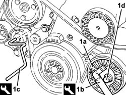
- The device is tensioned automatically and by means of a pre-loaded spring imparting the correct tension on the belt during fitting and the automatic recovery of the clearance produced during normal operation.
- Fit the plug in the cam tensioner.
- Raise the power unit with the hydraulic device under the gearbox.
- Tighten the nuts securing the gearbox side flexible mounting to the mounting bracket to torque.
| Value - daNm | Fastening | Component | Ø | |
|---|---|---|---|---|
| 3 | (Mount) 5.8 | Nuts | GEARBOX SIDE RUBBER MOUNT | M10X1.25 |
- Tighten the nuts securing the braking system control unit (NFR) to the mounting bracket to torque.
| Value - daNm | Fastening | Component | Ø | |
|---|---|---|---|---|
| 1.5 | Nuts | HYDRAULIC AND ELECTRONIC CONTROL UNIT | M8 |
- Connect the electrical connection for the braking system electronic control unit (NFR).
| Description | Connector | |
|---|---|---|
| Braking system control unit (NFR) | M051 |
- Tighten the reaction rod fixing bolt to torque.
| Value - daNm | Fastening | Component | Ø | |
|---|---|---|---|---|
| (body) 5 | Bolt | POWER UNIT REACTION ROD | M10 |
- Remove the hydraulic lift.
See in Op. 1048A56 UPPER RESONATOR - R.R.
See in Op. 1048B44 RIGID air supply PIPE from heat exchanger to intake manifold - R.R.
See in Op. 7040D50 ENGINE COMPARTMENT UPPER SOUND INSULATION SHIELD - R.R.
See in Op. 1016A10 SOUND-PROOFING COVER - R.R.
See in Op. 7055B64 Engine compartment DUST SEAL in front wheel arch (one), left or right - R.R.
See in Op. 7055B42 FRONT WHEEL ARCH LINER (one), left or right - R.R.
See in Op. 7055B54 PROTECTION/GUARD under engine - R.R.
See in Op. 4450B04 Right FRONT WHEEL (one) - R.R.
- Connect the battery terminal.
- Remove the vehicle from the lift.
Removing
- Position the vehicle on a lift.
- Open the boot and disconnect the negative battery terminal.
See in Op. 7040D50 ENGINE COMPARTMENT UPPER SOUND INSULATION SHIELD - R.R.
See in Op. 7055B54 PROTECTION/GUARD under engine - R.R.
See in Op. 4450B04 Right FRONT WHEEL (one) - R.R.
See in Op. 7055B42 FRONT WHEEL ARCH LINER (one), left or right - R.R.
See in Op. 7055B64 Engine compartment DUST SEAL in front wheel arch (one), left or right - R.R.
1. Undo the bolt fixing the reaction rod to the bodyshell.
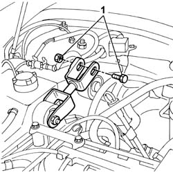
- Position a hydraulic lift under the gearbox to support the power unit.
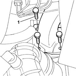
1. Undo the bolts fixing the engine support to the gearbox.
- Gently lower the hydraulic lift until it is resting on the crossmember.
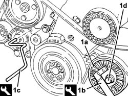
1. Adjust the moving tensioner (1a) for the single drive belt using the spanner (1b), then insert the tool (1c) in the opening in the tensioner.
| Description | Code | Function | |
|---|---|---|---|
| 1b | Spanner | 1.860.966.000 |
| Description | Code | Function | |
|---|---|---|---|
| 1c | Lock | 1.870.645.000 | Tensioning auxiliary shaft belt |
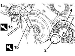
2. Remove the protective plug for the auxiliar shaft drive belt cam tensioner.
3. Undo the bolt retaining the cam tensioner.
4. Remove the auxiliary shaft drive belt.
Refitting
- Fit the single drive belt on the pullies.
Avoid the belt coming into contact with oil or solvents that could alter the flexibility of the rubber with a resulting loss of adhesion. Also check that the belt shows no signs of cracks or cuts or else it will have to be played.
1. Rotate the cam tensioner (1a) using the tool (1b) until the clip (1c) can be released easily, then lock the bolt (1d) fixing the cam tensioner.
| Description | Code | Function | |
|---|---|---|---|
| 1b | Spanner | 1.860.968.000 | Tensioning auxiliary shaft belt |
| Description | Code | Function | |
|---|---|---|---|
| 1c | Lock | 1.870.645.000 | Tensioning auxiliary shaft belt |
| Value - daNm | Fastening | Component | Ø | |
|---|---|---|---|---|
| 5 | Bolt | SINGLE BELT MOVING TENSIONER VARIOUS | M10 |
- The device is tensioned automatically and by means of a pre-loaded spring imparting the correct tension on the belt during fitting and the automatic recovery of the clearance produced during normal operation.
- Fit the plug in the cam tensioner.
- Raise the power unit with the hydraulic device under the gearbox.
- Tighten the bolts fixing the engine support, gearbox side.
| Value - daNm | Fastening | Component | Ø | |
|---|---|---|---|---|
| (Gearbox side) 5 | Bolts | POWER UNIT GEAR BOX END RIGID MOUNT | M10 |
- Tighten the bolt fixing the reaction rod to torque.
| Value - daNm | Fastening | Component | Ø | |
|---|---|---|---|---|
| (body) 5 | Bolt | POWER UNIT REACTION ROD | M10 |
- Remove the hydraulic lift.
See in Op. 4450B04 Right FRONT WHEEL (one) - R.R.
See in Op. 7055B42 FRONT WHEEL ARCH LINER (one), left or right - R.R.
See in Op. 7055B64 Engine compartment DUST SEAL in front wheel arch (one), left or right - R.R.
See in Op. 7055B54 PROTECTION/GUARD under engine - R.R.
See in Op. 7040D50 ENGINE COMPARTMENT UPPER SOUND INSULATION SHIELD - R.R.
- Connect the battery terminal.
Removing
- Position the vehicle on a lift.
- Open the boot, remove the cover on the left hand side and disconnect the negative battery lead.
See in Op. 7040D50 ENGINE COMPARTMENT UPPER SOUND INSULATION SHIELD - R.R.
See in Op. 4450B04 Right FRONT WHEEL (one) - R.R.
- Raise the vehicle on the lift.
See in Op. 7055B54 PROTECTION/GUARD under engine - R.R.
See in Op. 7055B42 FRONT WHEEL ARCH LINER (one), left or right - R.R.
- < R1 > (right side)
See in Op. 7055B64 Engine compartment DUST SEAL in front wheel arch (one), left or right - R.R.
- < R1 > (right side)
See in Op. 1048A50 air inlet pipe to turbocharger - r + r
See in Op. 1048A21 AIR INLET HOSE FROM INTAKE TO FILTER - R.R.
See in Op. 1048A10 COMPLETE AIR FILTER -R.R.
See in Op. 1016A40 Ignition COIL COVER on cylinder head - R.R.
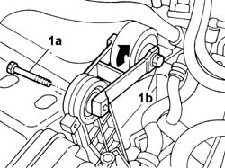
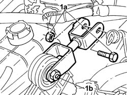
1. Undo the bolt (1a), loosen the bolt (1b) and rotate the reaction rod connecting rod.
- Raise the vehicle on the lift.
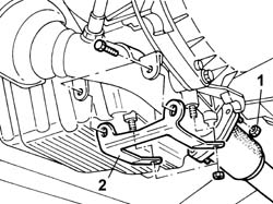
1. Undo the nuts fixing the catalytic converter to the centre section of the exhaust pipe.
2. Remove the mounting bracket for the front section of the exhaust pipe.
- Lower the vehicle on the lift, then position a hydraulic lift under the bellhousing.
1. Undo the nuts securing the engine mount to the gearbox.
- Gradually lower the hydraulic lift and rest the gearbox on the front crossmember.
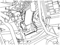
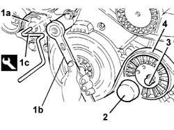
1. Align the reference openings in the tensioner (1a) using the spanner (1b); fit the lock (1c) when the openings are aligned.
| Description | Code | Function | |
|---|---|---|---|
| 1c | Lock | 1.870.645.000 | Automatic belt tensioner retainer for auxiliary components belt |
2. Remove the protective cover.
3. Undo the bolt retaining the cam tensioner.
4. Release and remove the auxiliary shaft drive belt.
Refitting
- Fit the auxiliary shaft drive belt on the pullies.
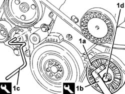
1. Fit the tool (1b) in the openings in the cam tensioner (1a) and tension the belt until the lock (1c) can be inserted in the reference openings in the automatic belt tensioner; tighten the bolt (1d) fixing the cam in this position. Check that the tool (1c) can be inserted in the reference openings and extracted; this means that the belt is correctly tensioned.
| Description | Code | Function | |
|---|---|---|---|
| 1b | Spanner | 1.860.968.000 | Tensioning auxiliary shaft belt |
| Description | Code | Function | |
|---|---|---|---|
| 1c | Lock | 1.870.645.000 | Automatic belt tensioner retainer for auxiliary components belt |
| Value - daNm | Fastening | Component | Ø | |
|---|---|---|---|---|
| 1d | 5 | Bolt | VARIOUS S D BELT CAM TENSIONER | M10 X 1.25 |
- Position a hydraulic lift under the gearbox bellhousing.
- Screw in and tighten the bolt fixing the engine support to the gearbox to the recommended torque.
| Value - daNm | Fastening | Component | Ø | |
|---|---|---|---|---|
| 5 | Bolt | POWER UNIT GEAR BOX END RIGID MOUNT | M10 X 1.25 |
- Raise the vehicle on the lift.
- Tighten the nuts fixing the catalytic converter to the centre section of the exhaust pipe.
| Value - daNm | Fastening | Component | Ø | |
|---|---|---|---|---|
| (to cable centre section) 2.8 | Nut | CATALYTIC CONVERTER (ONE) | M8 |
- Fit the mounting bracket for the front section of the exhaust pipe.
| Value - daNm | Fastening | Component | Ø | |
|---|---|---|---|---|
| (on engine oil sump) 4 | Nut | CATALYTIC CONVERTER MOUNT | M10 X 1.25 |
| Value - daNm | Fastening | Component | Ø | |
|---|---|---|---|---|
| (to catalytic converter) 2.8 | Bolt | CATALYTIC CONVERTER MOUNT | M8 |
- Lower the vehicle on the lift.
- Connect the connecting rod to the reaction rod and secure it using the bolts.
| Value - daNm | Fastening | Component | Ø | |
|---|---|---|---|---|
| (to bracket on bodyshell) 5 | Bolt | POWER UNIT REACTION ROD | M10 X 1.25 |
| Value - daNm | Fastening | Component | Ø | |
|---|---|---|---|---|
| (to engine support) 5 | Bolt | POWER UNIT REACTION ROD | M10 X 1.25 |
See in Op. 1048A10 COMPLETE AIR FILTER -R.R.
See in Op. 1048A21 AIR INLET HOSE FROM INTAKE TO FILTER - R.R.
See in Op. 1048A50 air inlet pipe to turbocharger - r + r
See in Op. 1016A40 Ignition COIL COVER on cylinder head - R.R.
See in Op. 7055B64 Engine compartment DUST SEAL in front wheel arch (one), left or right - R.R.
See in Op. 7055B42 FRONT WHEEL ARCH LINER (one), left or right - R.R.
See in Op. 7055B54 PROTECTION/GUARD under engine - R.R.
See in Op. 4450B04 Right FRONT WHEEL (one) - R.R.
See in Op. 7040D50 ENGINE COMPARTMENT UPPER SOUND INSULATION SHIELD - R.R.
- Connect the negative battery lead.
- Remove the vehicle from the lift.
Removing
- Position the vehicle on a lift.
- Open the boot, remove the cover on the left hand side and disconnect the negative battery lead.
See in Op. 7040D50 ENGINE COMPARTMENT UPPER SOUND INSULATION SHIELD - R.R.
See in Op. 4450B04 Right FRONT WHEEL (one) - R.R.
- Raise the vehicle on the lift.
See in Op. 7055B54 PROTECTION/GUARD under engine - R.R.
See in Op. 7055B42 FRONT WHEEL ARCH LINER (one), left or right - R.R.
- (right side)
See in Op. 7055B64 Engine compartment DUST SEAL in front wheel arch (one), left or right - R.R.
- (right side)
See in Op. 1048A28 vacuum air circuit resonator pipe - r+r
See in Op. 1048A21 AIR INLET HOSE FROM INTAKE TO FILTER - R.R.
See in Op. 1048A10 COMPLETE AIR FILTER -R.R.
See in Op. 1016A40 Ignition COIL COVER on cylinder head - R.R.
1. Undo the bolt (1a), loosen the bolt (1b) and rotate the reaction rod connecting rod.
- Raise the vehicle on the lift.
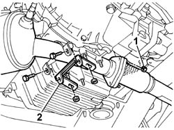
1. Undo the nuts fixing the catalytic converter to the centre section of the exhaust pipe.
2. Remove the mounting bracket for the front section of the exhaust pipe.
- Lower the vehicle on the lift, then position a hydraulic lift under the bellhousing.
1. Undo the bolts fixing the engine support to the gearbox.
- Gradually lower the hydraulic lift and rest the gearbox on the front crossmember.
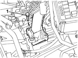
1. Align the reference openings in the tensioner (1a) using the spanner (1b); fit the lock (1c) when the openings are aligned.
| Description | Code | Function | |
|---|---|---|---|
| 1c | Lock | 1.870.465.000 | Retainer for automatic belt tensioner |
2. Remove the protective cover.
3. Undo the bolt retaining the cam tensioner.
4. Release and remove the auxiliary shaft drive belt.
Refitting
- Fit the auxiliary shaft drive belt on the pullies.
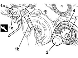
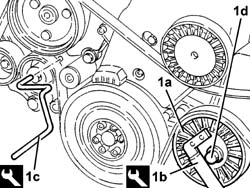
1. Fit the tool (1b) in the openings in the cam tensioner (1a) and tension the belt until the lock (1c) can be inserted in the reference openings in the automatic belt tensioner; tighten the bolt (1d) fixing the cam in this position.
| Description | Code | Function | |
|---|---|---|---|
| 1b | Spanner | 1.860.968.000 | Tensioning auxiliary shaft belt |
| Description | Code | Function | |
|---|---|---|---|
| 1c | Lock | 1.870.645.000 | Automatic belt tensioner retainer for single components belt |
| Value - daNm | Fastening | Component | Ø | |
|---|---|---|---|---|
| 1d | 5 | Bolt | VARIOUS S D BELT CAM TENSIONER | M10 X 1.25 |
1. Check that the tool (1c) can be inserted in the reference openings and extracted; this means that the belt is correctly tensioned.
- Position a hydraulic lift under the gearbox bellhousing.
- Screw in and tighten the bolt fixing the engine support to the gearbox to the recommended torque.
| Value - daNm | Fastening | Component | Ø | |
|---|---|---|---|---|
| 5 | Bolt | POWER UNIT GEAR BOX END RIGID MOUNT | M10 X 1.25 |
- Raise the vehicle on the lift.
- Tighten the nuts fixing the catalytic converter to the centre section of the exhaust pipe.
| Value - daNm | Fastening | Component | Ø | |
|---|---|---|---|---|
| (to cable centre section) 2.8 | Nut | CATALYTIC CONVERTER (ONE) | M8 |
- Fit the mounting bracket for the front section of the exhaust pipe.
| Value - daNm | Fastening | Component | Ø | |
|---|---|---|---|---|
| (on engine oil sump) 4 | Nut | CATALYTIC CONVERTER MOUNT | M10 X 1.25 |
| Value - daNm | Fastening | Component | Ø | |
|---|---|---|---|---|
| (to catalytic converter) 2.8 | Bolt | CATALYTIC CONVERTER MOUNT | M8 |
- Lower the vehicle on the lift.
- Connect the connecting rod to the reaction rod and secure it using the bolts.
| Value - daNm | Fastening | Component | Ø | |
|---|---|---|---|---|
| (to bracket on bodyshell) 5 | Bolt | POWER UNIT REACTION ROD | M10 X 1.25 |
| Value - daNm | Fastening | Component | Ø | |
|---|---|---|---|---|
| (to engine support) 5 | Bolt | POWER UNIT REACTION ROD | M10 X 1.25 |
See in Op. 1048A10 COMPLETE AIR FILTER -R.R.
See in Op. 1048A21 AIR INLET HOSE FROM INTAKE TO FILTER - R.R.
See in Op. 1048A28 vacuum air circuit resonator pipe - r+r
See in Op. 1016A40 Ignition COIL COVER on cylinder head - R.R.
See in Op. 7055B64 Engine compartment DUST SEAL in front wheel arch (one), left or right - R.R.
See in Op. 7055B42 FRONT WHEEL ARCH LINER (one), left or right - R.R.
See in Op. 7055B54 PROTECTION/GUARD under engine - R.R.
See in Op. 4450B04 Right FRONT WHEEL (one) - R.R.
See in Op. 7040D50 ENGINE COMPARTMENT UPPER SOUND INSULATION SHIELD - R.R.
- Connect the negative battery lead.
- Remove the vehicle from the lift.
Removing
- Position the vehicle on a lift.
See in Op. 4450B04 Right FRONT WHEEL (one) - R.R.
- Raise the vehicle on the lift.
See in Op. 7055B64 Engine compartment DUST SEAL in front wheel arch (one), left or right - R.R.
See in Op. 7055B42 FRONT WHEEL ARCH LINER (one), left or right - R.R.
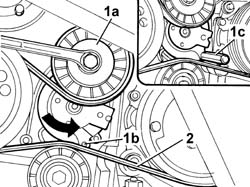
1. Use a spanner on the moving tensioner (1a) in the direction illustrated in the diagram until the centering openings (1b) are aligned, then insert a 4 mm diameter retaining pin (1c) to keep the tensioner in this "slack belt" position.
2. Release and remove the auxiliary shaft drive belt.
Refitting
- Fit the auxiliary shaft drive belt on the pullies.
- Keeping the moving tensioner in this "slack belt" position using a spanner, remove the retaining pin.
See in Op. 7055B42 FRONT WHEEL ARCH LINER (one), left or right - R.R.
See in Op. 7055B64 Engine compartment DUST SEAL in front wheel arch (one), left or right - R.R.
See in Op. 4450B04 Right FRONT WHEEL (one) - R.R.
- Remove the vehicle from the lift.
Parts & tools for this job Staging For 2002 Lancia Thesis
- PARTEngine gasket setSearch: Lancia Thesis 2002 engine gasket set
- TOOLTorque wrenchSearch: 3/8 inch torque wrench
- TOOLFeeler gauge setSearch: feeler gauge set
Links open Amazon search results in a new tab. As an Amazon Associate I earn from qualifying purchases.