
POWER UNIT with manual gearbox - R.R.
- Make
- Lancia
- Model
- Thesis Factory Service Manual
- Year
- 2002–2009
- Section
- Engine and power unit › POWER UNIT with manual gearbox - R.R.
POWER UNIT with manual gearbox - R.R.
Removing
- Position the vehicle on a lift.
See in Op. 7040D50 ENGINE COMPARTMENT UPPER SOUND INSULATION SHIELD - R.R.
See in Op. 5040A10 Air conditioning coolant circuit - Drying and Repressurizing
- Open the boot, remove the cover on the left hand side and disconnect the negative battery lead.
- Raise the vehicle on the lift.
See in Op. 7055B54 PROTECTION/GUARD under engine - R.R.
- Position a suitable container for collecting the engine coolant.
- Raise the lift.
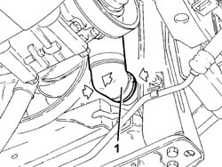
1. Disconnect the lower radiator pipe.
See in Op. 4450B12 Front WHEELS (two) - R.R.
See in Op. 1048A21 AIR INLET HOSE FROM INTAKE TO FILTER - R.R.
See in Op. 1048A23 Cold AIR INTAKE for air filter - R.R.
See in Op. 1048A28 vacuum air circuit resonator pipe - r+r
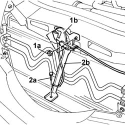
1. Undo the fixing nuts (1a) and remove the bonnet lock (1b) from the housing in the crossmember.
2. Undo the lower bolt (2a) and remove the lock reinforcement bracket (2b).
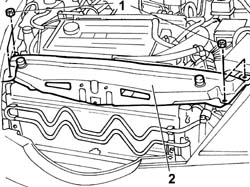
1. Undo the retaining nuts.
2. Remove the front crossmember.
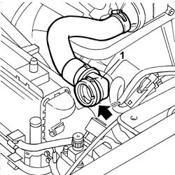
1. Disconnect the upper radiator pipe.
- Remove the container placed under the engine for collecting the drained coolant.
To disconnect both pipes, press the springs, manually, and release the rapid pipe connector from the attachments on the radiator.
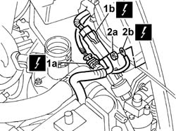
1. Disconnect the electrical connections (1a) and (1b) for the engine cables/fan-radiator cables coupling.
| Description | Connector | |
|---|---|---|
| 1a | Front/radiator coupling | D009A |
| Description | Connector | |
|---|---|---|
| 1b | Front/radiator coupling | D009B |
2. Undo the nut (2a) and disconnect the earth lead (2b) from the bodyshell.
| Description | Connector | |
|---|---|---|
| 2b | Right front earth | C011 |
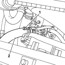
1. Undo the retaining bolt.
2. Disconnect the air conditioning system compressor pipe from the compressor.
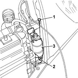
1. Undo the bolts fixing the air conditioning system pipes to the drier filter.
2. Undo the nuts fixing the filter to the condenser.
3. Remove the drier filter.
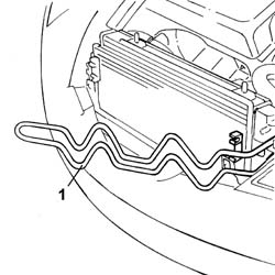
1. Release the power assisted steering system cooling coil from the condenser.
See in Op. 7055B42 FRONT WHEEL ARCH LINER (one), left or right - R.R.
See in Op. 7055B64 Engine compartment DUST SEAL in front wheel arch (one), left or right - R.R.
See in Op. 7210E10 FRONT BUMPER
1. Release the radiator-condenser-fan assembly from the lower fastenings and remove it through the top of the engine compartment.
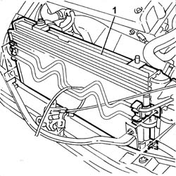
See in Op. 1048A10 COMPLETE AIR FILTER -R.R.
See in Op. 1016A40 Ignition COIL COVER on cylinder head - R.R.
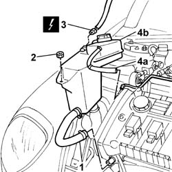
1. Disconnect the coolant pipe retaining band on the cylinder head.
2. Undo the nut fixing the expansion tank (this nut also fastens the windscreen washer fluid reservoir).
3. Disconnect the electrical connection for the engine coolant level.
| Description | Connector | |
|---|---|---|
| 3 | Engine coolant level sensor | K026 |
4. Disconnect the pipe (4a) and lift up the expansion tank (4b) and remove it.
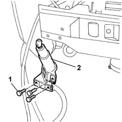
1. Undo the bolts fixing the headlamp washer jets to the crossmember.
2. Move the headlamp washer jets away from the working area.
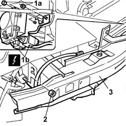
- Release the electrical wiring positioned under the crossmember, disconnecting the electrical connections for the horns.
| Description | Connector | |
|---|---|---|
| High tone horn | P010 |
| Description | Connector | |
|---|---|---|
| Low tone horn | P011 |
| Description | Connector | |
|---|---|---|
| High tone horn | P010 |
| Description | Connector | |
|---|---|---|
| Low tone horn | P011 |
1. Undo the nuts (1a) fastening the Cruise Control to the crossmember, disconnect the electrical connection (1b) and remove the device.
| Description | Connector | |
|---|---|---|
| 1b | Cruise control system control unit (NAC) | M087 |
2. Undo the nuts fixing the crossmember to the strut.
3. Remove the lower crossmember.
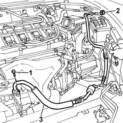
1. Undo the fixing bolt and disconnect the pipe from the connector on the compressor.
2. Undo the fixing nut and separate the front section of the pipe from the rear section.
3. Remove the front section of the air conditioning system high pressure pipe.
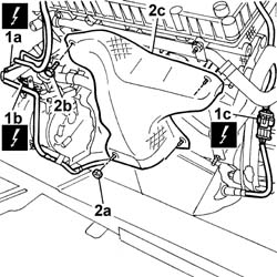
1. Disconnect the electrical connector (1a) for the front Lambda sensor and the compressor coupling (1b) from the compressor; disconnect the electrical connector (1c) for the rear Lambda sensor.
| Description | Connector | |
|---|---|---|
| 1a | Lambda sensor on catalyzer | K017 |
| Description | Connector | |
|---|---|---|
| 1b | Air conditioning compressor engagement electro-magnet | L020 |
| Description | Connector | |
|---|---|---|
| Lambda sensor on catalyzer | K017 |
2. Undo the three nuts (2a) and the bolt (2b), then remove the exhaust manifold heat shield (2c).
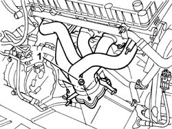
1. Undo the nuts fixing the catalytic converter to the exhaust manifold.
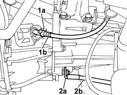
1. Lift up the retaining spring (1a) and release the oil pipe (1b) for the hydraulic clutch release cylinder.
2. Undo the nut (2a) and disconnect the earth lead (2b) from the gearbox.
1. Disconnect the electrical connection from the engine management control unit; release the electrical wiring from the retaining bands.
| Description | Connector | |
|---|---|---|
| 1 | Engine management control unit | M010B |
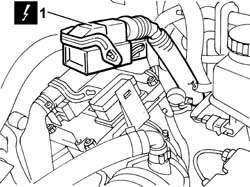
1. Disconnect the electrical connection from the ABS electronic control unit.
| Description | Connector | |
|---|---|---|
| 1 | Braking system control unit (NFR) | M051 |
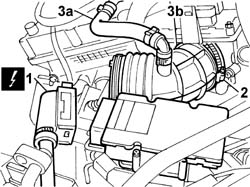
2. Disconnect the retaining band for the hose connected to the resonator from the throttle casing.
3. Disconnect the engine oil vapour recovery pipe (3a) from the cylinder head, then remove the hose (3b).
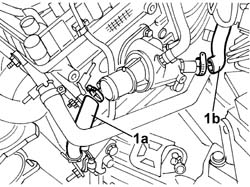
1. Disconnect the coolant supply pipe (1a) to the engine oil heat exchanger and the heater supply pipe (1b) from the thermostat.
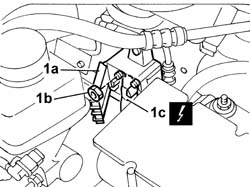
1. Open the protective cover (1a), loosen the nut (1b) and disconnect the starter motor supply lead (1c).
| Description | Connector | |
|---|---|---|
| 1c | Starter motor | A020A |
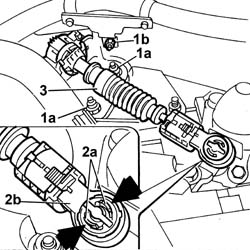
1. Undo the three nuts (1a) fastening the flexible cables mounting bracket to the gearbox and the nut (1b) securing the starter motor earth lead mounting bracket.
2. Press the two tabs (2a) and lift up the head (2b) until it is released from the ball joint.
- Carry out this operation on the other flexible cable.
3. Position the bracket, complete with flexible cables, outside of the working area.
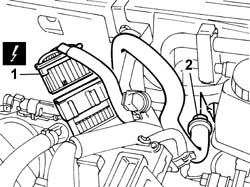
1. Disconnect the electrical connection for the engine/dashboard cable loom coupling.
2. Disconnect the vacuum intake pipe from the brake servo.
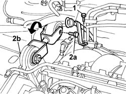
1. Undo the bolt fixing the engine oil dipstick pipe.
2. Remove the bolt (2a) and loosen the bolt (2b) securing the reaction rod; rotate the reaction rod forwards.
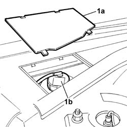
- Remove the protective cover (1a), undo the power assisted steering fluid reservoir cap (1b) and draw off the fluid in the reservoir using a special syringe.
1. Disconnect the retaining band for the fluid supply pipe from the reservoir on the power assisted steering pump.
2. Undo the connector on the power assisted steering pump supplying pressurized fluid to the power assisted steering box
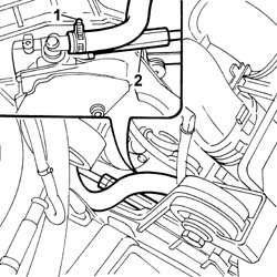
1. Disconnect the connector for the anti-evaporation system pipe.
- Discharge the fuel pressure with the tool connected to the valve on the single fuel manifold pipe.
| Description | Code | Function | |
|---|---|---|---|
| Rapid attachment connector | 1.870.684.000 | Single fuel manifold pipe complete with injectors |
2. Disconnect the rapid attachment connector for the fuel supply pipe on the fuel manifold; release the pipe from the retaining band on the intake chamber.
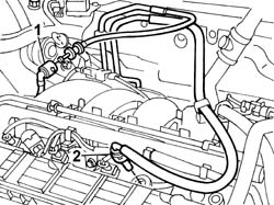
- Raise the lift.
1. Undo the nuts fixing the flange joining the front and rear sections of the exhaust pipe.
2. Undo the fastenings for the mounting bracket (2a) and remove the front section of the exhaust pipe (2b).
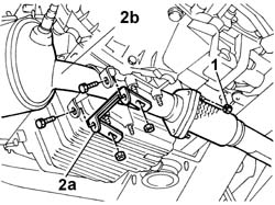
1. Disconnect the band for the left and right driveshafts secured to the differential and the intermediate driveshaft.
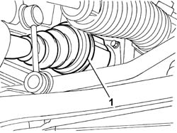
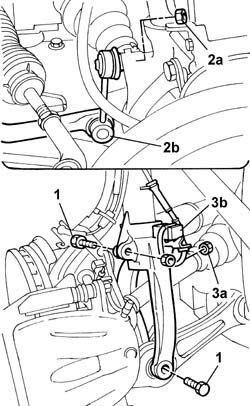
1. Undo the fixing bolts.
2. Undo the upper fixing nut (2a) and disconnect the end of the anti-roll bar connecting rod (2b).
3. Undo the fixing nut (3a) and move the accelerometer sensor (3b), complete with mounting bracket, aside.
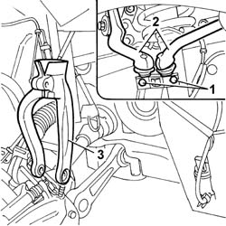
1. Undo the fixing bolts.
2. Separate the two heads from the suspension housing.
3. Remove the suspension fork.
- Move the steering knuckle backwards and release the three-lobe joints for the driveshafts from the housing in the differential and the intermediate shaft.
Take great care not to damage the brake fluid pipes and the electrical leads for the sensors, if necessary, release them from the bands on the steering knuckles.
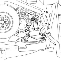
1. Undo the nut (1a) fixing the timing side engine support (1b) to the supporting crossmember.
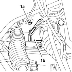
1. Undo the nut (1a) fixing the rear engine support (1b) to the supporting crossmember.
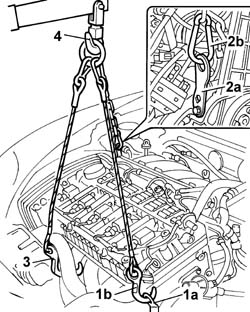
1. Position a bracket (1a) on the cylinder head and secure the chain and hook assembly (1b) to it.
2. Position a bracket (2a) on the reaction rod support and secure the chain and hook assembly (1b) to it.
3. Secure the chain and hook assembly to the exhaust manifold.
4. Secure the chains to the hydraulic lifting device and tension the engine.
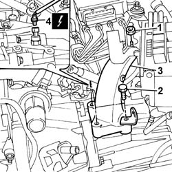
1. Undo the nut fixing the engine support to the flexible mounting.
2. Undo the bolts fixing the engine support to the gearbox.
3. Remove the engine support from the engine compartment.
4. Disconnect the electrical connection on the gearbox for the reverse gear engagement sensor.
| Description | Connector | |
|---|---|---|
| 4 | Reversing lights switch | I020 |
- Raise the engine slightly, turn the timing side towards the front of the vehicle and the gearbox side towards the rear, then remove the power unit from the engine compartment.
- Position the power unit on a special support and remove the hoist, making sure that the unit is properly balanced.
Refitting
- Secure the power unit with chains for hoisting to the hydraulic lifting device.
- Position the power unit in the vehicle, fitting the timing side engine support and the rear support on the flexible mounting bearings.
- Tighten the nut fixing the rear engine support to the supporting crossmember.
| Value - daNm | Fastening | Component | Ø | |
|---|---|---|---|---|
| (to crossmember) 5 | Nut | RIGID REAR SUPPORT POWER UNIT | M10 X 1.25 |
- Tighten the nut fixing the timing side engine support to the supporting crossmember.
| Value - daNm | Fastening | Component | Ø | |
|---|---|---|---|---|
| (to crossmember) 5 | Nut | RIGID ENGINE MOUNT, TIMING SIDE | M10 X 1.25 |
- Position the engine suport and secure it to the bell housing.
| Value - daNm | Fastening | Component | Ø | |
|---|---|---|---|---|
| (on gearbox) 5 | Bolt | POWER UNIT GEAR BOX END RIGID MOUNT | M10 X 1.25 |
- Tighten the nut fixing the engine support to the flexible mounting.
| Value - daNm | Fastening | Component | Ø | |
|---|---|---|---|---|
| (on flexible mounting) 5 | Bolt | POWER UNIT GEAR BOX END RIGID MOUNT | M10 X 1.25 |
- Connect the electrical connection on the gearbox for the reversing lights switch.
| Description | Connector | |
|---|---|---|
| Reversing lights switch | I020 |
- Release the engine from the supporting hooks.
- Remove the brackets positioned for attaching the engine supporting hooks.
- Fit the three-lobe joints for the driveshafts in their housings in the differential and the intermediate shaft.
- Connect the two ends of the suspension and secure them using fastening bolts.
| Value - daNm | Fastening | Component | Ø | |
|---|---|---|---|---|
| 3.4 | Bolt | FRONT SHOCK ABSORBERS (S.M.) | M8 |
- Tighten the upper nut securing the anti-roll bar connecting rod end.
| Value - daNm | Fastening | Component | Ø | |
|---|---|---|---|---|
| 5.5 | Nut | FRONT ANTI-ROLL BAR JOINTS | M10 X 1.25 |
- Tighten the bolts fixing the fork to the steering knuckle.
| Value - daNm | Fastening | Component | Ø | |
|---|---|---|---|---|
| (to the lower front rod) 9 | Bolt | FRONT DAMPER FORK ON WISHBONE | M12 x 1.25 |
| Value - daNm | Fastening | Component | Ø | |
|---|---|---|---|---|
| (to the shock absorber) 11.6 | Bolt | FRONT DAMPER FORK ON WISHBONE | M12 X 1.25 |
- Position the bracket complete with accelerometer sensor and secure it using the bolt.
- Fit the retaining bands for the left and right driveshaft boots on the differential and on the intermediate driveshaft.
- Position the first section of the exhaust pipe and secure it to the flange joined with the rear section using the nuts.
| Value - daNm | Fastening | Component | Ø | |
|---|---|---|---|---|
| (to cable centre section) 2.8 | Nut | CATALYTIC CONVERTER (ONE) | M8 |
- Position the mounting bracket for the front section of the exhaust pipe.
| Value - daNm | Fastening | Component | Ø | |
|---|---|---|---|---|
| (to catalytic converter) 2.8 | Bolt | CATALYTIC CONVERTER MOUNT | M8 |
| Value - daNm | Fastening | Component | Ø | |
|---|---|---|---|---|
| (on engine oil sump) 4 | Nut | CATALYTIC CONVERTER MOUNT | M10 X 1.25 |
- Tighten the nuts fixing the catalytic converter to the exhaust manifold.
| Value - daNm | Fastening | Component | Ø | |
|---|---|---|---|---|
| 2.8 | Nut | CATALYTIC CONVERTER (ONE) | M8 |
- Fit the exhaust manifold heat shield.
- Fit the oil pipe for the hydraulic clutch release cylinder and secure it using the retaining spring.
- Connect the earth lead to the bellhousing.
- Position the mounting bracket for the gearbox flexible control cables and secure it using the fixing nuts.
| Value - daNm | Fastening | Component | Ø | |
|---|---|---|---|---|
| (on bellhousing) 1.7 | Nut | MANUAL GEARBOX LEVER SUPPORT (F) | M8 |
- Connect the ends of the flexible cables to the ball joints.
- Fasten the mounting bracket for the starter motor earth lead using the nut.
- Connect the electrical connection for the engine/dashboard cable loom coupling.
- Connect the vacuum intake pipe to the brake servo.
- Connect the starter motor supply lead, then reposition the protective cover.
- Connect the electrical connection for the ABS electronic control unit.
- Connect the electrical connection for the engine management control unit; secure the electrical wiring to the retaining bands.
| Description | Connector | |
|---|---|---|
| Engine management control unit | M010B |
- Connect the hose connected to the resonator to the throttle casing using the band.
- Connect the oil vapour recovery pipe to the tappet cover using the band.
- Connect the coolant supply pipe to the engine oil heat exchanger and the heater supply pipe to the thermostat.
- Connect the rapid attachment connector for the fuel supply pipe on the fuel manifold; secure the pipe to the retaining band on the intake chamber.
- Connect the connector for the fuel vapour recovery pipe.
- Connect the retaining band for the fluid supply pipe from the reservoir on the power assisted steering pump.
- Tighten the connector on the power assisted steering pump supplying pressurized fluid to the power assisted steering box.
- Tighten the bolt fixing the engine oil dipstick pipe.
- Position the connecting rod for the reaction rod and tighten the fixing bolts.
| Value - daNm | Fastening | Component | Ø | |
|---|---|---|---|---|
| (to bracket on bodyshell) 5 | Bolt | POWER UNIT REACTION ROD | M10 X 1.25 |
| Value - daNm | Fastening | Component | Ø | |
|---|---|---|---|---|
| (to engine support) 5 | Bolt | POWER UNIT REACTION ROD | M10 X 1.25 |
- Connect the upper radiator pipe to the thermostat.
- Position the front section of the air conditioning system high pressure pipe and connect it to the rear section.
- Connect the high pressure pipe connector to the compressor.
See in Op. 1048A10 COMPLETE AIR FILTER -R.R.
- Position the radiator-condenser-fan assembly on the lower supports.
- Fit the drier filter and fasten it to the condenser.
- Connect the air conditioning system pipes to the drier filter.
- Connect the air conditioning system connector to the compressor.
- Connect the electrical connection for the air conditioning compressor coupling.
| Description | Connector | |
|---|---|---|
| Air conditioning compressor engagement electro-magnet | L020 |
- Connect the electrical connection for the front Lambda sensor.
| Description | Connector | |
|---|---|---|
| Lambda sensor on catalyzer | K017 |
- Connect the electrical connection for the rear Lambda sensor.
- Secure the power assisted steering system cooling coil to the condenser.
- Connect the electrical connections for the engine cables/fan-radiator cables coupling.
| Description | Connector | |
|---|---|---|
| Front/radiator coupling | D009A |
| Description | Connector | |
|---|---|---|
| Front/radiator coupling | D009B |
- Connect the earth lead to the bodyshell.
- Connect the pipe with the upper rapid connector to the radiator.
- Position the expansion tank and secure it using the nut.
- Connect the pipe to the cylinder head.
- Connect the coolant recovery pipe.
- Connect the electrical connection for the engine coolant level.
| Description | Connector | |
|---|---|---|
| Engine coolant level sensor | K026 |
- Position the lower crossmember and secure it to the strut and the wings.
| Value - daNm | Fastening | Component | Ø | |
|---|---|---|---|---|
| 2.5 | Nut | CROSSMEMBER | M8 |
- Fit the Cruise Control and secure it to the lower crossmember using the nuts, then connect the electrical connection.
| Description | Connector | |
|---|---|---|
| Cruise control system control unit (NAC) | M087 |
- Secure the electrical wiring positioned under the crossmember and connect the electrical connections for the horns.
| Description | Connector | |
|---|---|---|
| High tone horn | P010 |
| Description | Connector | |
|---|---|---|
| High tone horn | P010 |
| Description | Connector | |
|---|---|---|
| Low tone horn | P011 |
| Description | Connector | |
|---|---|---|
| Low tone horn | P011 |
- Position the headlamp washer jets and secure them to the lower crossmember.
- Connect the lower radiator pipe.
- Fit the upper front crossmember.
- Fit the bonnet lock on the crossmember complete with reinforcement bracket.
See in Op. 7210E10 FRONT BUMPER
See in Op. 1048A28 vacuum air circuit resonator pipe - r+r
See in Op. 1048A23 Cold AIR INTAKE for air filter - R.R.
See in Op. 1048A21 AIR INLET HOSE FROM INTAKE TO FILTER - R.R.
See in Op. 1016A40 Ignition COIL COVER on cylinder head - R.R.
See in Op. 7055B64 Engine compartment DUST SEAL in front wheel arch (one), left or right - R.R.
See in Op. 7055B42 FRONT WHEEL ARCH LINER (one), left or right - R.R.
See in Op. 4450B12 Front WHEELS (two) - R.R.
See in Op. 0010T20 Engine REFRIGERANT FLUID - Change
See in Op. 7055B54 PROTECTION/GUARD under engine - R.R.
- Connect the negative battery lead and close the boot.
See in Op. 5040A10 Air conditioning coolant circuit - Drying and Repressurizing
See in Op. 7040D50 ENGINE COMPARTMENT UPPER SOUND INSULATION SHIELD - R.R.
- Remove the vehicle from the lift.
- The power assisted steering system is self-bleeding, proceed as described below.
- Start the engine and carry out 4 - 5 complete steering wheel rotation cycles (left and right).
- Top up the power assisted steering fluid level in the reservoir.
Removing
- Position the vehicle on a lift.
- Make sure that the ignition key is in the OFF position, then open the boot, remove the cover on the left hand side and disconnect the negative battery lead.
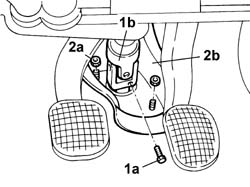
1. Undo the bolt (1a) fixing the steering column (1b) to the steering box pinion.
2. Undo the fixing nuts (1a) and remove the protective boot (2b) from the vehicle floor.
See in Op. 7040D50 ENGINE COMPARTMENT UPPER SOUND INSULATION SHIELD - R.R.
See in Op. 5040A10 Air conditioning coolant circuit - Drying and Repressurizing
See in Op. 7055B54 PROTECTION/GUARD under engine - R.R.
- Position a suitable container for collecting the engine coolant.
- Raise the lift.
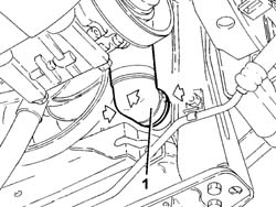
1. Disconnect the lower radiator pipe.
See in Op. 4450B02 Left FRONT WHEEL (one) - R.R.
See in Op. 4450B04 Right FRONT WHEEL (one) - R.R.
- Raise the lift
See in Op. 7055B64 Engine compartment DUST SEAL in front wheel arch (one), left or right - R.R.
See in Op. 7055B42 FRONT WHEEL ARCH LINER (one), left or right - R.R.
See in Op. 7210E10 FRONT BUMPER
- Lower the lift
See in Op. 1048B44 RIGID air supply PIPE from heat exchanger to intake manifold - R.R.
See in Op. 1016A40 Ignition COIL COVER on cylinder head - R.R.
See in Op. 1048A50 air inlet pipe to turbocharger - r + r
See in Op. 1048A21 AIR INLET HOSE FROM INTAKE TO FILTER - R.R.
See in Op. 1048A10 COMPLETE AIR FILTER -R.R.
See in Op. 1048A54 TURBOCHARGER air inlet HOSE from rigid pipe - R.R.
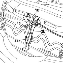
1. Undo the fixing nuts (1a) and remove the bonnet lock (1b) from the housing in the crossmember.
2. Undo the lower bolt (2a) and remove the lock reinforcement bracket (2b).
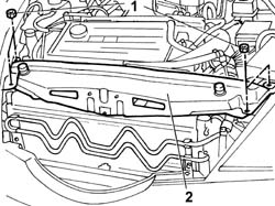
1. Undo the retaining bolts.
2. Remove the front crossmember.
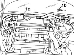
1. Undo the fixing bolt on the compressor (1a) and the bolt fixing the flange (1b) and remove the climate control system coolant return pipe (1c).
- Disconnect the electrical connections for the horns.
| Description | Connector | |
|---|---|---|
| High tone horn | P010 |
| Description | Connector | |
|---|---|---|
| High tone horn | P010 |
| Description | Connector | |
|---|---|---|
| Low tone horn | P011 |
| Description | Connector | |
|---|---|---|
| Low tone horn | P011 |
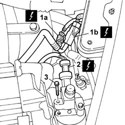
1. Disconnect the electrical connections for the engine cables/fan-radiator cables coupling.
| Description | Connector | |
|---|---|---|
| 1a | Front/radiator coupling | D009A |
| Description | Connector | |
|---|---|---|
| 1b | Front/radiator coupling | D009B |
2. Disconnect the electrical connection from the air conditioning system pressure switch.
| Description | Connector | |
|---|---|---|
| 2 | Linear sensor (for climate control) | K120 |
3. Undo the bolt fixing the air conditioning system pipe to the drier filter.
1. Undo the nut (1a) and disconnect the earth lead (1b) from the bodyshell.
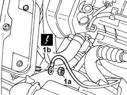
1. Lift up the retaining spring (1a) and release the oil pipe (1b) for the hydraulic clutch release cylinder.
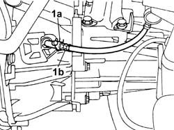
1. Open the protective cover (1a), loosen the nut (1b) and disconnect the starter motor supply lead (1c).
| Description | Connector | |
|---|---|---|
| 1c | Starter motor | A020A |
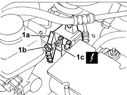
1. Undo the three nuts (1a) fastening the flexible cables mounting bracket to the gearbox and the nut (1b) securing the starter motor earth lead mounting bracket.
2. Press the two tabs (2a) and lift up the head (2b) until it is released from the ball joint.
- Carry out this operation on the other flexible cable.
3. Position the bracket, complete with flexible cables, outside of the working area.
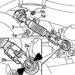
1. Disconnect the electrical connection for the engine management control unit.
| Description | Connector | |
|---|---|---|
| 1 | Engine management control unit | M010A |
2. Disconnect the electrical connection from the fuel vapour recovery solenoid valve.
| Description | Connector | |
|---|---|---|
| 2 | Fuel vapour recovery solenoid valve | L010 |
3. Disconnect the vacuum intake pipe from the brake servo.
4. Disconnect the fuel vapour intake pipe from the intake chamber.
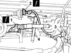
1. Disconnect the engine coolant supply pipe (1a) and return pipe (1b) from the passenger compartment heater.
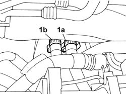
1. Release the fastening band (1a) and remove the turbocharger engine coolant return pipe (1b).
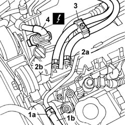
2. Disconnect the fuel supply pipe (2a) and the return pipe (2b) from the fuel manifold.
3. Release the fuel pipes from the band on the intake chamber.
4. Disconnect the electrical connection for the engine/dashboard cable loom coupling.
| Description | Connector | |
|---|---|---|
| 4 | Front/dashboard coupling | D001 |
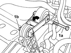
1. Undo the bolt (1a), loosen the bolt (1b) and rotate the reaction rod connecting rod.
1. Release the fastening band (1a) and disconnect the engine coolant pipe (1b) on the cylinder head.
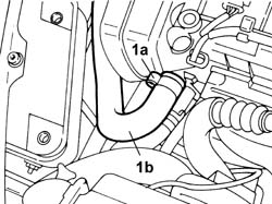
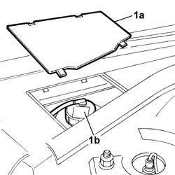
1. Remove the protective cover (1a), undo the power assisted steering fluid reservoir cap (1b) and draw off the fluid in the reservoir using a special syringe.
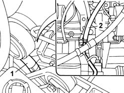
1. Disconnect the supply pipe from the reservoir to the power assisted steering pump.
2. Disconnect the fluid return pipe from the power assisted steering box.
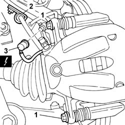
1. Loosen the bolts fixing the brake caliper to the hub.
2. Remove the brake pipe retaining band.
3. Disconnect the electrical connection for the brake pad wear sensor.
| Description | Connector | |
|---|---|---|
| 3 | Left brake pad wear sensor (switch) | K020 |
| Description | Connector | |
|---|---|---|
| 3 | Right brake pad wear sensor (switch) | K021 |
Take great care not to damage the brake fluid pipes and the electrical leads for the sensors, if necessary, release them from the bands on the steering knuckles.
- Undo the retaining bolt and remove the ABS flywheel sensor.
1. Undo the retaining bolt.
2. Undo the upper fixing nut (2a) and disconnect the end of the anti-roll bar connecting rod (2b).
3. Undo the fixing nut (3a) and move the accelerometer sensor (3b), complete with mounting bracket, aside.
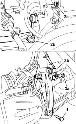
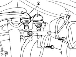
1. Undo the fixing bolts.
2. Separate the two heads from the suspension housing.
3. Remove the fixing bolts (3a) and remove the brake caliper (3b).
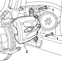
- Repeat the operations on the brake caliper and the suspension damper on the opposite side.
- Disconnect the electrical connection for the bodyshell accelerometer sensor (left side).
| Description | Connector | |
|---|---|---|
| Left front vertical acceleration sensor | K006 |
| Description | Connector | |
|---|---|---|
| Right front vertical acceleration sensor | K007 |
See in Op. 1076B70 EXHAUST PIPE BETWEEN PRECATALYZER AND CATALYZER - R.R.
1. Undo the nut fixing the engine support to the flexible mounting.
2. Undo the bolts fixing the engine support to the gearbox.
3. Remove the engine support from the engine compartment.
4. Disconnect the electrical connection on the gearbox for the reverse gear engagement sensor.
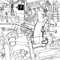
1. Position the tool for supporting the power unit-chassis assembly (1a), complete with hydraulic jack, under the housings in the power unit support frame (1b).
| Description | Code | Function | |
|---|---|---|---|
| 1a | Power unit support frame | 1.870.835.000 | Removing power unit-chassis |
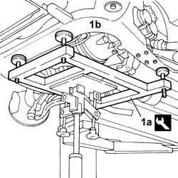
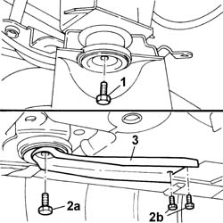
1. Undo the bolts fixing the front supports.
2. Undo the bolts (2a) fixing the rear supports and the bolts (2b) fixing the brackets.
3. Remove the brackets.
- Lower the power unit-chassis assembly moving it away from the vehicle.
1. Disconnect the pipes from the power assisted steering system cooling coil.
2. Disconnect the heat exchanger air intake pipe.
3. Release the supercharging by-pass solenoid valve from the bracket.
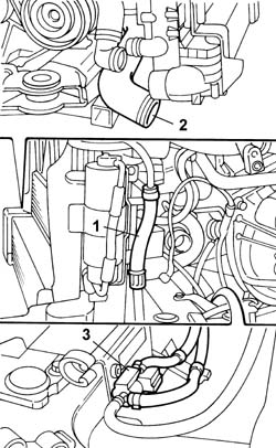
- Remove the engine cooling radiator complete with fan, heat exchanger, condenser and power assisted steering system cooling coil.
1. Disconnect the band fastening the left driveshaft to the intermediate driveshaft and release the driveshaft.
2. Disconnect the power steering fluid supply pipe.
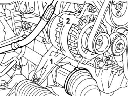
1. Disconnect the band fastening the right driveshaft to the differential and release the driveshaft.
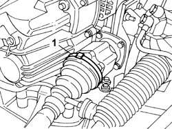
- Remove the engine support connecting rod.
1. Fit a suitable size bracket on the timing side.
Position suitable to washers to prevent damage to the flexible mounting.
2. Fit a suitable size bracket on the gearbox side.
3. Secure the chain and hook assembly to the brackets fitted previously and to the hydraulic lifting device.
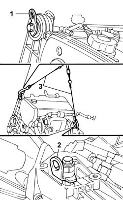
1. Undo the nut (1a) fixing the timing side engine support (1b) to the supporting crossmember.
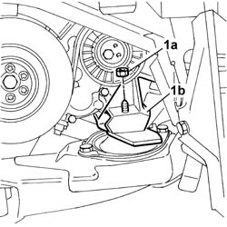
1. Undo the nut (1a) fixing the rear engine support (1b) to the supporting crossmember.
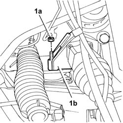
- Raise the power unit.
- Position the power unit on a special support and remove the hoist, making sure that the unit is properly balanced.
Refitting
- Position the power unit-chassis support tool on the hydraulic jack, then position the power unit support frame on the power unit-chassis assembly support tool by the seats.
| Description | Code | Function | |
|---|---|---|---|
| Power unit support frame | 1.870.835.000 | Removing power unit-chassis |
- Secure the power unit with chains for hoisting to the hydraulic lifting device.
- Position the power unit on the chassis, fitting the timing side engine support and the rear support on the flexible mounting bearings.
- Tighten the nut fixing the rear engine support to the supporting crossmember.
| Value - daNm | Fastening | Component | Ø | |
|---|---|---|---|---|
| (to crossmember) 5 | Nut | RIGID REAR SUPPORT POWER UNIT | M10 X 1.25 |
- Tighten the nut fixing the timing side engine support to the supporting crossmember.
| Value - daNm | Fastening | Component | Ø | |
|---|---|---|---|---|
| (to crossmember) 5 | Nut | RIGID ENGINE MOUNT, TIMING SIDE | M10 X 1.25 |
- Release the engine from the supporting chains.
- Remove the brackets positioned for attaching the power unit supporting hooks.
- Position the connecting rod for the reaction rod and tighten the fixing bolt.
| Value - daNm | Fastening | Component | Ø | |
|---|---|---|---|---|
| (to engine support) 5 | Bolt | POWER UNIT REACTION ROD | M10 X 1.25 |
- Fit the three-lobe joints for the driveshafts in their housings in the differential and the intermediate shaft.
- Fit the boots on both sides and secure the retaining bands.
- Fit the engine cooling radiator complete with fan, heat exchanger, condenser and power assisted steering system cooling coil.
- Connect the power steering fluid supply pipe.
- Connect the pipes to the power assisted steering system cooling coil.
- Connect the heat exchanger air intake pipe.
- Attach the supercharging by-pass solenoid valve from the bracket.
- Raise the power unit-chassis until the front and rear flexible supports correspond with the housings in the bodyshell.
- Fit the brackets and tighten the fixing bolts.
- Tighten the rear support fixing bolts.
See in Op. 1076B70 EXHAUST PIPE BETWEEN PRECATALYZER AND CATALYZER - R.R.
- Position the engine suport and secure it to the bell housing.
| Value - daNm | Fastening | Component | Ø | |
|---|---|---|---|---|
| (on gearbox) 5 | Bolt | POWER UNIT GEAR BOX END RIGID MOUNT | M10 X 1.25 |
- Tighten the nut fixing the engine support to the flexible mounting.
| Value - daNm | Fastening | Component | Ø | |
|---|---|---|---|---|
| (on flexible mounting) 5 | Bolt | POWER UNIT GEAR BOX END RIGID MOUNT | M10 X 1.25 |
- Connect the electrical connection on the gearbox for the reversing lights switch.
- Position the bracket complete with bodyshell accelerometer sensor (left side) and secure it using the bolt.
- Fit the brake caliper on both sides and screw in the fixing bolts without tightening them.
- Connect the two ends of the suspension on both sides and secure them using the fastening bolts.
| Value - daNm | Fastening | Component | Ø | |
|---|---|---|---|---|
| 3.4 | Bolt | FRONT SHOCK ABSORBERS (S.M.) | M8 |
- Tighten the upper nut securing the anti-roll bar connecting rod on both sides.
| Value - daNm | Fastening | Component | Ø | |
|---|---|---|---|---|
| 5.5 | Nut | FRONT ANTI-ROLL BAR JOINTS | M10 X 1.25 |
- Tighten the bolt fixing the fork to the steering knuckle on both sides.
| Value - daNm | Fastening | Component | Ø | |
|---|---|---|---|---|
| (to the lower front rod) 9 | Bolt | FRONT DAMPER FORK ON WISHBONE | M12 x 1.25 |
- Position the bracket complete with accelerometer sensor on both sides and secure it using the bolt.
- Fit the ABS sensor on both sides and position the cable in the special cable duct.
- Connect the electrical connection for the brake pad wear sensor.
| Description | Connector | |
|---|---|---|
| 3 | Left brake pad wear sensor (switch) | K020 |
| Description | Connector | |
|---|---|---|
| 3 | Right brake pad wear sensor (switch) | K021 |
Take great care not to damage the brake fluid pipes and the sensor electrical cables.
- Fasten the brake pipe retaining band.
- Tighten the bolts fixing the brake caliper to the hub.
- Connect the supply pipe from the reservoir to the power assisted steering pump.
- Connect the fluid return pipe to the power assisted steering box.
- Lower the lift.
- Connect the engine coolant pipe to the cylinder head.
- Position the connecting rod for the reaction rod and tighten the fixing bolts.
| Value - daNm | Fastening | Component | Ø | |
|---|---|---|---|---|
| (to bracket on bodyshell) 5 | Bolt | POWER UNIT REACTION ROD | M10 X 1.25 |
| Value - daNm | Fastening | Component | Ø | |
|---|---|---|---|---|
| (to engine support) 5 | Bolt | POWER UNIT REACTION ROD | M10 X 1.25 |
- Connect the electrical connection for the engine/dashboard cable loom coupling.
| Description | Connector | |
|---|---|---|
| Front/dashboard coupling | D001 |
- Connect the fuel supply and return pipe to the fuel manifold and secure the fuel pipes to the band on the intake chamber.
- Connect the turbocharger engine coolant return pipe.
- Connect the engine coolant supply pipe and return pipe to the passenger compartment heater.
- Connect the electrical connection for the engine management control unit.
| Description | Connector | |
|---|---|---|
| Engine management control unit | M010A |
- Connect the electrical connection from the fuel vapour recovery solenoid valve to the intake.
| Description | Connector | |
|---|---|---|
| Fuel vapour recovery solenoid valve | L010 |
- Connect the vacuum intake pipe to the brake servo.
- Connect the fuel vapour intake pipe to the intake chamber.
- Position the mounting bracket for the gearbox flexible control cables and secure it using the fixing nuts.
| Value - daNm | Fastening | Component | Ø | |
|---|---|---|---|---|
| (on bellhousing) 1.7 | Nut | MANUAL GEARBOX LEVER SUPPORT (F) | M8 |
- Connect the ends of the flexible cables to the ball joints.
- Fasten the mounting bracket for the starter motor earth lead using the nut.
- Connect the starter motor supply lead, then reposition the protective cover.
| Description | Connector | |
|---|---|---|
| Starter motor | A020A |
- Fit the oil pipe for the hydraulic clutch release cylinder and secure it using the retaining spring.
- Connect the earth lead to the bodyshell.
- Tighten the bolt fixing the air conditioning system pipe to the drier filter.
- Connect the electrical connection to the air conditioning system pressure switch.
| Description | Connector | |
|---|---|---|
| Linear sensor (for climate control) | K120 |
- Connect the electrical connections for the engine cables/fan-radiator cables coupling.
| Description | Connector | |
|---|---|---|
| Front/radiator coupling | D009A |
| Description | Connector | |
|---|---|---|
| Front/radiator coupling | D009B |
- Connect the electrical connections for the horns.
| Description | Connector | |
|---|---|---|
| High tone horn | P010 |
| Description | Connector | |
|---|---|---|
| High tone horn | P010 |
| Description | Connector | |
|---|---|---|
| Low tone horn | P011 |
| Description | Connector | |
|---|---|---|
| Low tone horn | P011 |
- Position the air conditioning system coolant return pipe and tighten the fixing bolt on the compressor and the flange fixing bolt.
- Fit the upper front crossmember and tighten the fixing bolts.
- Fit the bonnet lock on the crossmember complete with reinforcement bracket.
See in Op. 1048A54 TURBOCHARGER air inlet HOSE from rigid pipe - R.R.
See in Op. 1048A10 COMPLETE AIR FILTER -R.R.
See in Op. 1048A21 AIR INLET HOSE FROM INTAKE TO FILTER - R.R.
See in Op. 1048A50 air inlet pipe to turbocharger - r + r
See in Op. 1016A40 Ignition COIL COVER on cylinder head - R.R.
See in Op. 1048B44 RIGID air supply PIPE from heat exchanger to intake manifold - R.R.
- Raise the lift
See in Op. 7210E10 FRONT BUMPER
See in Op. 7055B42 FRONT WHEEL ARCH LINER (one), left or right - R.R.
See in Op. 7055B64 Engine compartment DUST SEAL in front wheel arch (one), left or right - R.R.
- Lower the lift
See in Op. 4450B04 Right FRONT WHEEL (one) - R.R.
See in Op. 4450B02 Left FRONT WHEEL (one) - R.R.
- Connect the lower radiator pipe.
See in Op. 7055B54 PROTECTION/GUARD under engine - R.R.
- Connect the negative battery lead and close the boot.
See in Op. 5040A10 Air conditioning coolant circuit - Drying and Repressurizing
See in Op. 7040D50 ENGINE COMPARTMENT UPPER SOUND INSULATION SHIELD - R.R.
- Remove the vehicle from the lift.
- Position the protective boot on the vehicle floor and tighten the fixing nuts.
- Connect the steering column to the steering box pinion and tighten the fixing bolt.
- The power assisted steering system is self-bleeding, proceed as described below.
- Refill the power assisted steering fluid reservoir with the recommended amount of fluid.
- Start the engine and carry out 4 - 5 complete steering wheel rotation cycles (left and right).
- Top up the power assisted steering fluid level in the reservoir.
- Close the cap and position the protective cover.
Removing
- Position the vehicle on a lift.
- Open the boot and disconnect the negative battery terminal.
See in Op. 7040D50 ENGINE COMPARTMENT UPPER SOUND INSULATION SHIELD - R.R.
See in Op. 1016A10 SOUND-PROOFING COVER - R.R.
See in Op. 5040A10 Air conditioning coolant circuit - Drying and Repressurizing
See in Op. 7055B54 PROTECTION/GUARD under engine - R.R.
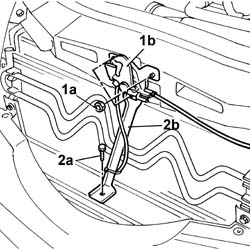
1. Undo the fixing nuts (1a) and remove the bonnet lock (1b) from its housing in the crossmember.
2. Undo the lower nut (2a) and remove the lock reinforcement bracket (2b).
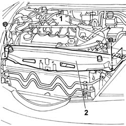
1. Undo the fixing bolts.
2. Remove the upper front crossmember.
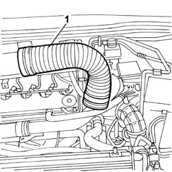
1. Remove the cold air intake pipe from the connector on the air filter.
- Have a suitable container for collecting the coolant ready.
- Raise the lift.
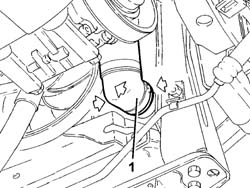
1. Disconnect the lower radiator pipe.
- Lower the lift.
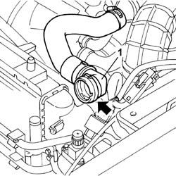
1. Disconnect the upper radiator pipe.
- Remove the container for collecting the engine coolant.
To disconnect both pipes, press the springs, manually, and release the rapid pipe connector from the attachments on the radiator.
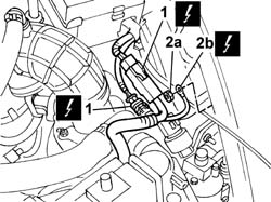
1. Disconnect the electrical connections (1a) and (1b) for the engine cables/fan-radiator cables coupling.
2. Undo the nut (2a) and disconnect the earth lead (2b) from the bodyshell.
| Description | Connector | |
|---|---|---|
| 1 | Front/radiator coupling | D009A |
| Description | Connector | |
|---|---|---|
| 1 | Front/radiator coupling | D009B |
| Description | Connector | |
|---|---|---|
| 2b | Right front earth | C011 |
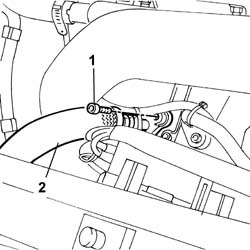
1. Undo the fixing bolt.
2. Disconnect the air conditioning system compressor pipe from the compressor.
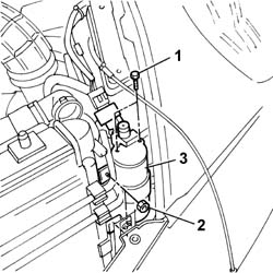
1. Undo the bolts fixing the air conditioning system pipes to the drier filter.
2. Undo the bolts fixing the filter to the condenser.
3. Remove the drier filter.
1. Release the power assisted steering system cooling coil from the condenser.
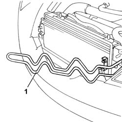
See in Op. 4450B12 Front WHEELS (two) - R.R.
See in Op. 7055B42 FRONT WHEEL ARCH LINER (one), left or right - R.R.
- (right side)
See in Op. 7055B64 Engine compartment DUST SEAL in front wheel arch (one), left or right - R.R.
- (right side)
See in Op. 7210E10 FRONT BUMPER
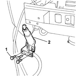
1. Undo the fixing bolts.
2. Remove the headlamp washer jets from the housing in the crossmember.
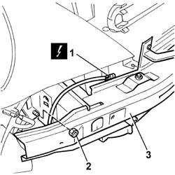
1. Disconnect the acceleration sensor electrical connection.
| Description | Connector | |
|---|---|---|
| 1 | Left front vertical acceleration sensor | K006 |
| Description | Connector | |
|---|---|---|
| 1 | Right front vertical acceleration sensor | K007 |
Release the electrical wiring and the jet water pipe from the bands under the crossmember.
2. Undo the fixing nuts.
3. Remove the lower crossmember.
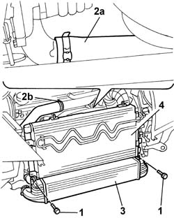
1. Undo the bolts fixing the air/air heat exchanger to the radiator.
2. Disconnect the two heat exchanger pipes from the connector (2a) on the turbocharger and from the connector (2b) on the intake air pipe.
3. Remove the air/air heat exchanger complete with pipes.
4. Release the radiator-condenser-fan assembly from the lower fastenings and remove it through the top of the engine compartment.
- Raise the lift.
1. Undo the bolts fixing the resonator.
- Lower the lift.
2. Undo the bolts fixing the filter mounting bracket to the bodyshell.
3. Disconnect the engine oil vapour recirculation pipes from the tappet cover.
4. Disconnect the pipe connected to the air filter casing from the turbocharger.
5. Disconnect the electrical connection for flow meter.
6. Remove the air filter casing complete with filter element.
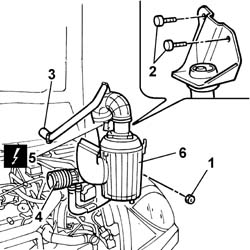
1. Undo the fixing bolt and disconnect the pipe from the connector on the compressor.
2. Undo the fixing nut and separate the front section of the pipe from the rear section.
3. Remove the front section of the air conditioning system high pressure pipe.
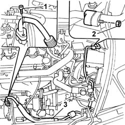
1. Undo the fixing nuts.
2. Release the turbocharger vane management solenoid valve from the crossmember and secure it to the power unit.
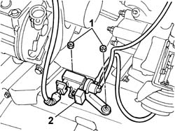
1. Disconnect the electrical connection for the engine management control unit.
| Description | Connector | |
|---|---|---|
| 1 | Engine management control unit | M010B |
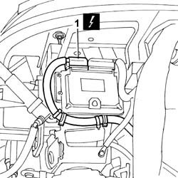
1. Lift up the retaining spring (1a) and release the oil pipe (1b) for the hydraulic clutch release cylinder.
2. Undo the nut (2a) and disconnect the earth lead (2b) from the gearbox.
| Description | Connector | |
|---|---|---|
| 2b | Battery earth | C001 |
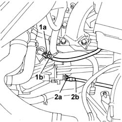
1. Disconnect the two heater coolant supply and return pipes from the thermostat.
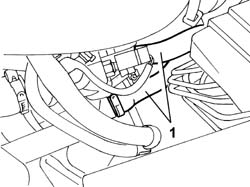
1. Move the pin (1a) back until it is released from the housing in the bracket (1b).
2. Press the two tabs (2a) and lift up the head (2b) until it is released from the ball joint.
- Carry out this operation on the other flexible cable.
3. Release the two flexible cables and place them well away from the power unit.
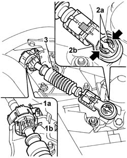
1. Open the protective cover (1a), loosen the nut (1b) and disconnect the starter motor supply lead (1c).
| Description | Connector | |
|---|---|---|
| 1c | Starter motor | A020A |
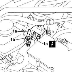
1. Disconnect the electrical connection for the heater plugs from the control unit.
2. Disconnect the vacuum pipe from the brake servo.
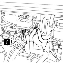
1. Disconnect the electrical connection for the engine/dashboard cable loom coupling.
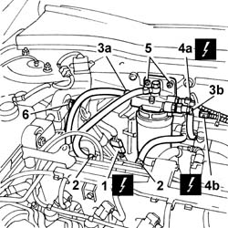
2. Disconnect the fuel pipes from the connectors on the return manifold.
3. Disconnect the fuel supply pipes (3a) and (3b) from the fuel filter.
4. Disconnect the electrical connections (4a) and (4b).
5. Remove the fuel filter assembly.
6. Undo the bolt on the bodyshell fixing the reaction rod.
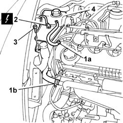
1. Disconnect the engine coolant recirculation pipe (1a) and the pipe (1b) connecting the coolant reservoir to the rigid pipe.
2. Disconnect the engine coolant level sensor.
| Description | Connector | |
|---|---|---|
| 2 | Engine coolant level sensor | K026 |
3. Release the engine wiring from the reservoir and undo the bolt fixing the reservoir.
4. Remove the engine coolant reservoir.
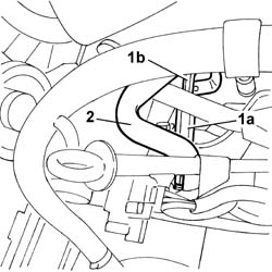
- Using a syringe, draw off the power assisted steering fluid from the reservoir.
1. Undo the connector (1a) and disconnect the pipe (1b) connecting the power assisted steering pump-steering box.
2. Disconnect the pipe connected to the fluid reservoir from the power assisted steering pump.
- Raise the lift.
1. Undo the nuts fixing the front section of the exhaust to the manifold.
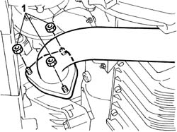
1. Disconnect the band for the left and right driveshafts secured to the differential and the intermediate driveshaft.
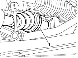
1. Undo the fixing bolts.
2. Undo the upper fixing nut (2a) and disconnect the end of the anti-roll bar (2b).
- Undo the fixing nut (3a) and move the acceleration sensor (3b) to the side.
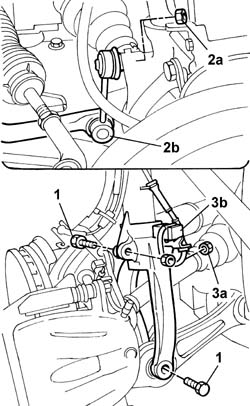
1. Undo the fixing bolts.
2. Separate the two heads from the suspension housing.
3. Remove the suspension fork.
- Move the steering knuckle backwards and release the three-lobe joints for the driveshafts from the housing in the differential and the intermediate shaft.
Take great care not to damage the brake fluid pipes and the electrical leads for the sensors, if necessary, release them from the bands on the steering knuckles.
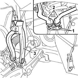
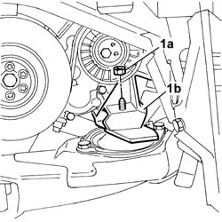
1. Undo the nut (1a) fixing the timing side engine support (1b) to the supporting crossmember.
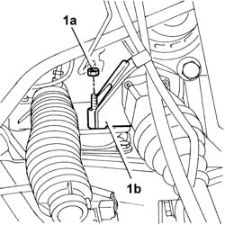
1. Undo the nut (1a) fixing the rear engine support (1b) to the supporting crossmember.
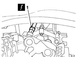
1. Disconnect the electrical connection on the gearbox for the reverse gear engagement sensor.
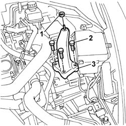
- Place some suitably thick material in between in order to be able to support the engine without it resting on the crossmember whilst removing the gearbox side engine support.
1. Undo the nut fixing the engine support to the flexible mounting.
2. Undo the bolts fixing the engine support to the gearbox.
3. Remove the engine support from the engine compartment.
1. Position a bracket (1a), complete with hook (1b), on the pressure pump support.
2. Fit the bracket (2a) in the gearbox side engine support housing and secure the chain and hook assembly (2b) to it.
3. Fit the brackets (3a) and (3b) to the exhaust manifold studs and secure the chain and hook assembly (3c) to them.
4. Secure the chains to the hydraulic lifting device and tension the engine.
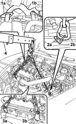
- Raise the power unit tilting the gearbox unit downwards, rotate the assembly so that the timing side is towards the front of the vehicle then, using the hydraulic lift, position the power unit on a suitable support.
Take great care not to damage the components fitted on the vehicle whilst rotating and removing the engine. Whilst rotating the power unit check that the gearbox-differential unit does not come into contact with the ABS unit; if necessary, disconnect the electrical connector for the ABS electro-hydraulic control unit.
Refitting
- Support the power unit using the hydraulic lift fitted with suitable chains and position the power unit in the special housing in the vehicle.
- Remove the chains, hooks and brackets fitted for supporting the power unit.
- Fit the gearbox side engine support.
- Tighten the bolts fixing the rigid support to the bellhousing to torque.
| Value - daNm | Fastening | Component | Ø | |
|---|---|---|---|---|
| (Gearbox side) 5 | Bolts | POWER UNIT GEAR BOX END RIGID MOUNT | M12 X 1.25 |
- Remove the material used for supporting the gearbox whilst removing-refitting the support.
- Connect the electrical connection on the gearbox for the reverse gear engagement sensor.
- Tighten the nut fixing the rear engine support to the supporting crossmember to torque.
| Value - daNm | Fastening | Component | Ø | |
|---|---|---|---|---|
| 5 | Nut | RIGID REAR SUPPORT POWER UNIT | M10 X 1.25 |
- Tighten the nut fixing the timing side engine support to the supporting crossmember to torque.
| Value - daNm | Fastening | Component | Ø | |
|---|---|---|---|---|
| 5 | Nut | RIGID ENGINE MOUNT, TIMING SIDE | M10 X 1.25 |
- Fit the suspension fork on the shock absorber.
- Position the steering knuckle in its original position, checking that the driveshafts are engaged in the housing in the differential and the intermediate driveshaft.
- Secure the two ends in the special housings in the suspension and tighten the fixing bolts to torque.
| Value - daNm | Fastening | Component | Ø | |
|---|---|---|---|---|
| 3.4 | Bolt | FRONT SHOCK ABSORBERS (S.M.) | M8 |
- Tighten the bolts fixing the forks to torque.
| Value - daNm | Fastening | Component | Ø | |
|---|---|---|---|---|
| 9 | Bolt | FRONT DAMPER FORK ON WISHBONE | M12 |
| Value - daNm | Fastening | Component | Ø | |
|---|---|---|---|---|
| 11.6 | Bolt | FRONT DAMPER FORK ON WISHBONE | M12 X 1.25 |
- Tighten the nuts fixing the anti-roll bar left and right ends to torque.
| Value - daNm | Fastening | Component | Ø | |
|---|---|---|---|---|
| 5.5 | Nut | FRONT ANTI-ROLL BAR JOINTS | M10 X 1.25 |
- Fit the left and right acceleration sensors in the housing in the fork and secure them using the fixing nuts.
- Secure the driveshafts to the differential and to the intermediate driveshaft using new bands.
- Tighten the nuts fixing the front section of the exhaust to the manifold.
| Value - daNm | Fastening | Component | Ø | |
|---|---|---|---|---|
| 2.8 | Nut | EXHAUST PIPE TO ENGINE | M8 |
- Connect the power assisted steering system pipes to the pump.
- Position the engine coolant reservoir in the special housing and reposition the electrical wiring in the special housing at the rear of the reservoir.
- Tighten the bolt fixing the reservoir to the windscreen washer fluid reservoir and to the bodyshell.
- Connect the electrical connection for the engine coolant level sensor.
| Description | Connector | |
|---|---|---|
| Engine coolant level sensor | K026 |
- Connect the engine coolant recirculation pipe and the pipe connecting the coolant reservoir to the rigid pipe.
- Screw in and then tighten the bolt fixing the reaction rod to the bodyshell to torque.
| Value - daNm | Fastening | Component | Ø | |
|---|---|---|---|---|
| (Bodyshell) 5 | Bolt | POWER UNIT REACTION ROD | M10 X 1.25 |
- Fit the fuel filter assembly in the special housing in the bulkhead.
- Tighten the nuts fixing the fuel filter to the bodyshell.
- Connect the electrical connections for the fuel filter.
- Connect the pipes to the pressure pump and return manifold and the return pipe from the return manifold to the reservoir to the filter filter.
- Connect the electrical connection for the engine/dashboard cable loom coupling.
- Connect the electrical connection for the heater plugs to the control unit.
- Connect the vacuum pipe to the brake servo single-acting valve.
- Connect the starter motor supply wiring to the special casing near the ABS unit.
| Description | Connector | |
|---|---|---|
| Starter motor | A020A |
- Connect the two flexible gear engagement and selector cables to the housing on the control linkage and the mounting bracket.
- Connect the two heater coolant supply and return pipes to the thermostat.
- Connect the fluid pipe for the hydraulic clutch release cylinder.
Check that the pipe is intact and that the fastening spring is fully inserted in the housing.
- Connect the battery earth lead to the gearbox.
| Description | Connector | |
|---|---|---|
| Battery earth | C001 |
- Connect the electrical connection for the engine management control unit.
| Description | Connector | |
|---|---|---|
| Engine management control unit | M010B |
- Position the turbocharger vane management solenoid valve in the housing in the engine supporting crossmember and tighten the fixing nuts.
- Position the air conditioning system high pressure pipe and connect it to the compressor connector tightening the fixing bolt.
- Connect the air conditioning system high pressure pipe to the coupling with the rear section of the pipe near the junction unit.
- Position the air filter casing in the engine compartment and tighten the bolts fixing the resonator and the mounting bracket.
Clean the air flow meter thoroughly to avoid damaging the sensitive element.
- Connect the electrical connection to the air flow meter.
- Connect the air pipe to the turbocharger and the engine oil vapour recirculation pipe to the tappet cover.
- Position the radiator/condenser/fan assembly in the special housing in crossmember engaging the rubber buffers on the lower part of the radiator in the special housing in the crossmember.
- Fit the air heat exchanger and tighten the bolts fixing it to the radiator.
- Connect the air/air heat exchanger air pipes.
- Fit the lower crossmember in the special housing in the struts.
- Tighten the nuts fixing the crossmember to torque.
| Value - daNm | Fastening | Component | Ø | |
|---|---|---|---|---|
| 2.5 | Nuts | CROSSMEMBER | M8 |
- Secure the engine wiring to the crossmember and fasten it using the bands.
- Connect the electrical connection for the acceleration sensor.
| Description | Connector | |
|---|---|---|
| Left front vertical acceleration sensor | K006 |
| Description | Connector | |
|---|---|---|
| Right front vertical acceleration sensor | K007 |
- Fit the headlamp washer jets to the crossmember and tighten the fixing nuts.
See in Op. 7210E10 FRONT BUMPER
See in Op. 7055B42 FRONT WHEEL ARCH LINER (one), left or right - R.R.
- (right side)
See in Op. 7055B64 Engine compartment DUST SEAL in front wheel arch (one), left or right - R.R.
- (right side)
See in Op. 4450B12 Front WHEELS (two) - R.R.
- Reposition the power assisted steering system cooling coil in the special housing on the radiator.
- Fit the drier filter and fasten it to the condenser using the fixing bolts.
- Connect the two air conditioning system pipes to the drier filter.
- Connect the air conditioning system pipe to the compressor.
- Connect the electrical connections for the engine cables/fan-radiator cables coupling.
| Description | Connector | |
|---|---|---|
| Front/radiator coupling | D009A |
| Description | Connector | |
|---|---|---|
| Front/radiator coupling | D009B |
- Connect the earth lead to the bodyshell and secure it using the nut.
| Description | Connector | |
|---|---|---|
| Right front earth | C011 |
- Connect the upper and lower engine coolant pipes to the radiator.
- Fit the cold air intake pipe to the connector on the air filter.
- Fit the upper front crossmember and tighten the fixing bolts to torque.
| Value - daNm | Fastening | Component | Ø | |
|---|---|---|---|---|
| 0.6 | Bolts | FRONT WING CROSSMEMBER HEADLAMP HOUSINGS | M6 |
- Fit the bonnet lid lock complete with bracket and tighten the nuts fixing it to the upper crossmember and the lower crossmember.
See in Op. 7055B54 PROTECTION/GUARD under engine - R.R.
See in Op. 5040A10 Air conditioning coolant circuit - Drying and Repressurizing
See in Op. 0010T20 Engine REFRIGERANT FLUID - Change
See in Op. 0010T21 ENGINE COOLANT - Check density and top up if necessary
- [0010T21]
See in Op. 0010T64 Brake and/or clutch fluid - Check level and top up, if necessary
See in Op. 1016A10 SOUND-PROOFING COVER - R.R.
See in Op. 7040D50 ENGINE COMPARTMENT UPPER SOUND INSULATION SHIELD - R.R.
- Close the bonnet lid and remove the vehicle from the lift.
Parts & tools for this job Staging For 2002 Lancia Thesis
- PARTClutch kitSearch: Lancia Thesis 2002 clutch kit
- TOOLClutch alignment toolSearch: clutch alignment tool
- FLUIDGear oilSearch: Lancia Thesis manual gearbox oil
Links open Amazon search results in a new tab. As an Amazon Associate I earn from qualifying purchases.