
Camshafts in camshaft housing - r.r - includes camshaft housing replacement, if necessary
- Make
- Fiat
- Model
- Ulysse Factory Service Manual
- Year
- 2002–2010
- Section
- Timing system › Camshafts in camshaft housing - r.r - includes camshaft housing replacement, if necessary
CAMSHAFTS IN CAMSHAFT HOUSING - R.R - INCLUDES CAMSHAFT HOUSING REPLACEMENT, IF NECESSARY
- Operation not available.
Removing
See
Op. 4450B04 RIGHT FRONT WHEEL - R.R
See
Op. 7055B91 RIGHT FRONT WHEEL ARCH LINER - R.R.
See
Op. 7055B54 UNDER ENGINE PROTECTION/GUARD - R.R.
See
Op. 1048B10 RIGID SUPPLY PIPE (ONE) BETWEEN TURBOCHARGER AND HEAT EXCHANGER -R.R.
See
Op. 5530B56 BATTERY DRIP TRAY COVER - R.R.
See
Op. 5010B18 HEATING VENTILATION UNIT AIR INTAKE - R+R
See
Op. 5050B34 WINDSCREEN WIPER ARM/S COMPLETE WITH BLADE - R+R
Both
See
Op. 7055A18 L/H OR R/H SIDE RUBBING STRIP (ONE) FOR FRONT DOOR - R+R
See
Op. 5050B38 WINDSCREEN WIPER ASSEMBLY - R+R OR REPAIR
See
Op. 1008C10 POWER UNIT UPPER SUPPORT - R R
See
Op. 1092G10 SINGLE ENGINE BELT - R.R
See
Op. 1024B54 ENGINE FLYWHEEL PROTECTION - R.R
See
Op. 1092A10 CRANKSHAFT PULLEY - R + R
See
Op. 1032D12 TIMING SYSTEM PROTECTIVE COVER(S) - R + R
See
Op. 1008A46 POWER UNIT RIGID SUPPORT - TIMING SIDE - R.R.
See
Op. 1032B10 TOOTHED TIMING BELT - R + R FOR TIMING ADJUSTMENT OR REPLACEMENT
Fit the timing side power unit rigid mount and tighten the bolts.
See
Op. 1048A10 AIR FILTER ASSEMBLY - R.R.
See
Op. 1048B22 AIR DELIVERY HOSE FROM HEAT EXCHANGER TO INTAKE MANIFOLD - R + R
See
Op. 1048A50 TURBOCHARGER AIR INTAKE PIPE - R.R.
1. Disconnect the electrical connection for the cam angle sensor.
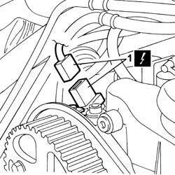
Carry out the same operation on all the injectors
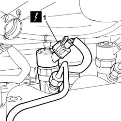
1. Disconnect the electrical connection for the injector.
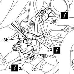
1. Disconnect the electrical connection for the glow plug wiring.
2. Disconnect the electrical connection for the engine coolant temperature sensor.
3. Disconnect electrical connection (3a), disconnect vacuum pipe (3b) and unscrew bolts (3c), remove intake manifold actuator control solenoid.
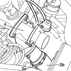
1. Disconnect vacuum pipes.
2. Open the retaining band (2a) and release air sleeve (1b).
3. Undo the bolts securing the throttle body.
4. Remove the throttle body.
1. Open the securing band (1a) using special pliers and destructive band (1b).
| Description | Code | Function | |
|---|---|---|---|
| Caliper | Open the retaining bands |
2. Remove the oil vapour pipe.
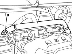
See
Op. 1080C54 EXHAUST GAS SUPPLY PIPE FROM E.G.R. VALVE TO INTAKE MANIFOLD - R.R.
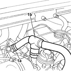
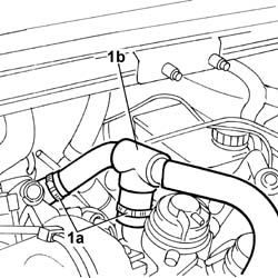
1. Open bands (1a), disconnect oil vapour pipe (1b) and move out of the working area.
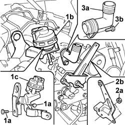
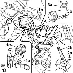
1. Undo bolts (1a), release head (1b) and remove Swirl valve (1c).
2. Undo nuts (2a), remove the mounting bracket (2b) and release from clips.
3. Undo bolt (3a) and remove the fitting (3b).
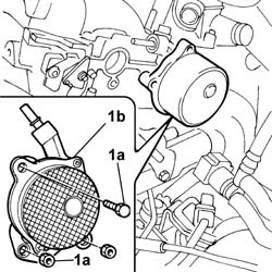
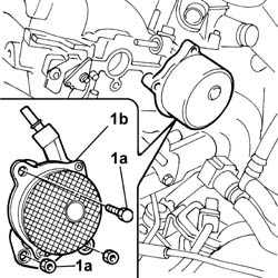
1. Undo bolt and nuts (1a) and remove the vacuum pump (1b).
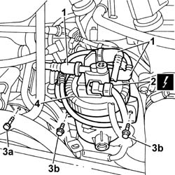
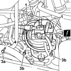
1. Undo the quick-release fittings and disconnect the fuel pipes
2. Disconnect the electrical connection.
3. Undo bolt (3a) securing the wiring channel and move out of the working area. Unscrew bolts (3b) securing the fuel filter.
4. Remove the fuel filter assembly.
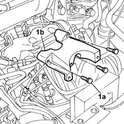
1. Undo bolts (1a) and remove the fuel filter mount (1b).
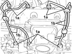
1. Undo the connectors (1a) and disconnect the rigid supply pipes from the single fuel supply pipe to the injectors (1b).
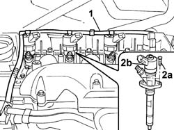
1. Disconnect the fuel return pipe from the injectors and move outside the working area.
2. Undo bolts (2a) and remove injector (2b) using the appropriate tool.
Carry out the same operation on all the injectors
| Description | Code | Function | |
|---|---|---|---|
| Extractor | Injector extractor |
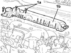
1. Undo bolts (1a) and remove the oil cover/separator (1b).
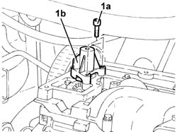
1. Undo bolts (1a) and remove the camshaft drive chain pretensioner (1b).
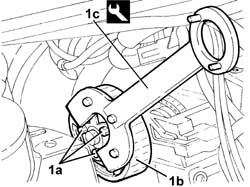
1. Loosen bolts (1a) securing the toothed driven pulley and flange (1b) using tool (1c) for counter-torque.
| Description | Code | Function | |
|---|---|---|---|
| Counter-torque | Counter-torque for exhaust side camshaft toothed driven pulley |
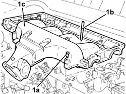
1. Undo bolts (1a) and studs (1b) and remove the single cylinder head extension (1c).
1. Remove camshafts (1a) complete with chain (1b).
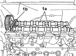
Refitting
1. Position camshafts (1a) complete with chain (1b).
2. Use the 8 mm calibrated pin (2a) for timing the exhaust side camshaft and position THE TIMING REFERENCE (2B) AT THE TOP when timing the inlet side camshaft.
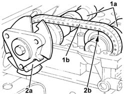
Apply silicon sealant to the matching surface between the single camshaft housing and the cylinder head.
1. Fit the single cylinder head extension and tighten the bolts to the specified torque in the tightening order shown.
references 1 to 8 indicate the studs and references 9 to 36 indicate the bolts.
| Value daNm | Fastening | Component | dia | |
|---|---|---|---|---|
1 1÷8 | Pretightening, Bolt | CYLINDER HEAD EXTENSION |
| Value daNm | Fastening | Component | dia | |
|---|---|---|---|---|
0.5 9÷36 | Stud | CYLINDER HEAD EXTENSION |
| Value daNm | Fastening | Component | dia | |
|---|---|---|---|---|
1 9÷36 | Tightening, Bolt | CYLINDER HEAD EXTENSION |
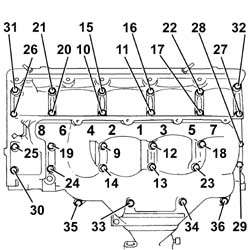
Position the camshaft drive chain tensioner and tighten the bolts.
1. Position the oil vapour cover/separator in its seat and screw in the bolts. Tighten to the required torque and follow the tightening order indicated.
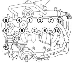
Remove the 8 mm calibrated pin.
Unscrew and remove the exhaust end camshaft flange using a tool for counter-torque.
| Description | Code | Function | |
|---|---|---|---|
| Counter-torque | Counter-torque |
Remove the exhaust camshaft oil seal. This operation is destructive for the oil seal, but take care not to damage the oil seal seat.
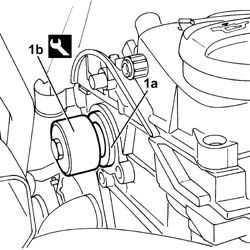
1. Fit a new oil seal on the exhaust side camshaft (1a) using a special fitting tool (1b).
| Description | Code | Function | |
|---|---|---|---|
| Fitting tool | Fit the oil seal on the camshaft |
| Description | Code | Function | |
|---|---|---|---|
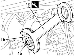
| 1c | Counter-torque | Counter-torque |
1. Fit flange (1a) into its seat on the exhaust end camshaft and tighten bolt (1b). Tighten to the specified torque using tool (1c) for counter-torque.
| Description | Code | Function | |
|---|---|---|---|
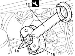
| 1c | Counter-torque | Counter-torque for exhaust side camshaft toothed driven pulley |
1. Fit toothed driven pulley (1a) into its proper seat on the exhaust end camshaft and tighten bolts (1b). Tighten to the specified torque using tool (1c) for counter-torque.
Fit the injectors in place and tighten the fixing nut checking the torque.
Fit the new rigid fuel supply pipes from the single fuel manifold pipe to the individual injectors in place and tighten the bands to the recommended torque.
Place the fuel filter mounting in position and tighten the fixing bolts.
Place the trim in position and tighten the fixing bolts.
Connect the fuel pipe rapid connectors to the filter.
Connect the electrical connection for the fuel filter sensor.
Fit the vacuum pump and tighten the nuts and bolts.
| daNm | Fastening | Component | dia |
|---|---|---|---|
| 2.0 | Bolts | VACUUM UNIT |
| daNm | Fastening | Component | dia |
|---|---|---|---|
| 2.0 | Nut | VACUUM UNIT |
Position the oil vapour recovery fitting and tighten the bolt.
Fit the Swirl valve.
Tighten the bolts and secure the ball joint in its seat.
Fit the oil vapour pipes and renew the retaining bands.
| Description | Code | Function | |
|---|---|---|---|
| Caliper | Open the retaining bands |
See
Op. 1080C54 EXHAUST GAS SUPPLY PIPE FROM E.G.R. VALVE TO INTAKE MANIFOLD - R.R.
Fit the throttle casing in place with the fixing bolts and connect the vacuum pipes to the valves on the throttle casing and fit the air hose and renew the retaining band.
Connect the electrical connection for the heater plug wiring.
Connect the electrical connection for the engine coolant level sensor.
Fit the intake manifold actuator control solenoid and tighten the bolts.
Connect the vacuum pipes to the intake manifold actuator solenoid.
Connect the electrical connections for the injectors.
Connect the electrical connection for the cam angle sensor.
See
Op. 1048A50 TURBOCHARGER AIR INTAKE PIPE - R.R.
See
Op. 1048B22 AIR DELIVERY HOSE FROM HEAT EXCHANGER TO INTAKE MANIFOLD - R + R
See
Op. 1048A10 AIR FILTER ASSEMBLY - R.R.
See
Op. 1032B10 TOOTHED TIMING BELT - R + R FOR TIMING ADJUSTMENT OR REPLACEMENT
See
Op. 1008A46 POWER UNIT RIGID SUPPORT - TIMING SIDE - R.R.
See
Op. 1032D12 TIMING SYSTEM PROTECTIVE COVER(S) - R + R
See
Op. 1092A10 CRANKSHAFT PULLEY - R + R
See
Op. 1024B54 ENGINE FLYWHEEL PROTECTION - R.R
See
Op. 1092G10 SINGLE ENGINE BELT - R.R
See
Op. 1008C10 POWER UNIT UPPER SUPPORT - R R
See
Op. 5050B38 WINDSCREEN WIPER ASSEMBLY - R+R OR REPAIR
See
Op. 7055A18 L/H OR R/H SIDE RUBBING STRIP (ONE) FOR FRONT DOOR - R+R
See
Op. 5050B34 WINDSCREEN WIPER ARM/S COMPLETE WITH BLADE - R+R
Both
See
Op. 5010B18 CLIMATE CONTROL UNIT AIR INTAKE - R.R.
See
Op. 5530B56 BATTERY DRIP TRAY COVER - R.R.
See
Op. 1048B10 RIGID SUPPLY PIPE (ONE) BETWEEN TURBOCHARGER AND HEAT EXCHANGER -R.R.
See
Op. 7055B54 UNDER ENGINE PROTECTION/GUARD - R.R.
See
Op. 7055B91 RIGHT FRONT WHEEL ARCH LINER - R.R.
See
Op. 4450B04 RIGHT FRONT WHEEL - R.R
Check engine fluid levels and top up where necessary.
Removing
See
Op. 4450B04 RIGHT FRONT WHEEL - R.R
See
Op. 7055B91 RIGHT FRONT WHEEL ARCH LINER - R.R.
See
Op. 7055B54 UNDER ENGINE PROTECTION/GUARD - R.R.
See
Op. 1048B10 RIGID SUPPLY PIPE (ONE) BETWEEN TURBOCHARGER AND HEAT EXCHANGER -R.R.
See
Op. 5530B56 BATTERY DRIP TRAY COVER - R.R.
See
Op. 5010B18 CLIMATE CONTROL UNIT AIR INTAKE - R.R.
See
Op. 5050B34 WINDSCREEN WIPER ARM/S COMPLETE WITH BLADE - R+R
Both
See
Op. 7055A18 L/H OR R/H SIDE RUBBING STRIP (ONE) FOR FRONT DOOR - R+R
See
Op. 5050B38 WINDSCREEN WIPER ASSEMBLY - R+R OR REPAIR
See
Op. 1008C10 POWER UNIT UPPER SUPPORT - R R
See
Op. 1092G10 SINGLE ENGINE BELT - R.R
See
Op. 1024B54 ENGINE FLYWHEEL PROTECTION - R.R
See
Op. 1092A10 CRANKSHAFT PULLEY - R + R
See
Op. 1032D12 TIMING SYSTEM PROTECTIVE COVER(S) - R + R
See
Op. 1008A46 POWER UNIT RIGID SUPPORT - TIMING SIDE - R.R.
See
Op. 1032B10 TOOTHED TIMING BELT - R + R FOR TIMING ADJUSTMENT OR REPLACEMENT
Fit the timing side power unit rigid mount and tighten the bolts.
See
Op. 1048A10 AIR FILTER ASSEMBLY - R.R.
See
Op. 1048B22 AIR DELIVERY HOSE FROM HEAT EXCHANGER TO INTAKE MANIFOLD - R + R
See
Op. 1048A50 TURBOCHARGER AIR INTAKE PIPE - R.R.
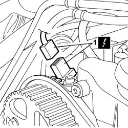
1. Disconnect the electrical connection for the cam angle sensor.
Carry out the same operation on all the injectors
1. Disconnect the electrical connection for the injector.
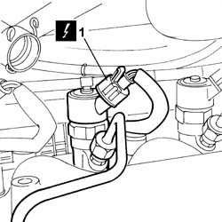
1. Disconnect the electrical connection for the glow plug wiring.
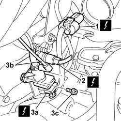
2. Disconnect the electrical connection for the engine coolant temperature sensor.
3. Disconnect electrical connection (3a), disconnect vacuum pipe (3b) and unscrew bolts (3c), remove intake manifold actuator control solenoid.
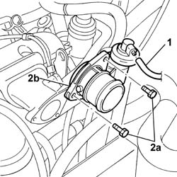
1. Disonnect the vacuum pipe.
2. Undo bolts (2a) and remove throttle body (2b).
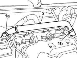
1. Open the securing band (1a) using special pliers and destructive band (1b).
2. Remove the oil vapour pipe.
| Description | Code | Function | |
|---|---|---|---|
| Caliper | Open the retaining bands |
See
Op. 1080C54 EXHAUST GAS SUPPLY PIPE FROM E.G.R. VALVE TO INTAKE MANIFOLD - R.R.
1. Open bands (1a), disconnect oil vapour pipe (1b) and move out of the working area.
1. Undo bolts (1a), release head (1b) and remove Swirl valve (1c).
2. Undo nuts (2a), remove the mounting bracket (2b) and release from clips.
3. Undo bolt (3a) and remove the fitting (3b).
1. Undo bolt and nuts (1a) and remove the vacuum pump (1b).
1. Undo the quick-release fittings and disconnect the fuel pipes
2. Disconnect the electrical connection.
3. Undo bolt (3a) securing the wiring channel and move out of the working area. Unscrew bolts (3b) securing the fuel filter.
4. Remove the fuel filter assembly.
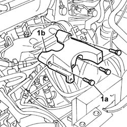
1. Undo bolts (1a) and remove the fuel filter mount (1b).
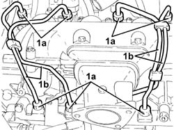
1. Undo the connectors (1a) and disconnect the rigid supply pipes from the single fuel supply pipe to the injectors (1b).
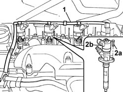
1. Disconnect the fuel return pipe from the injectors and move outside the working area.
2. Undo bolts (2a) and remove injector (2b) using the appropriate tool.
Carry out the same operation on all the injectors
| Description | Code | Function | |
|---|---|---|---|
| Extractor | Injector extractor |
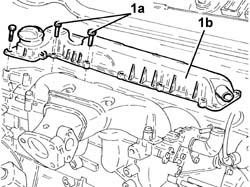
1. Undo bolts (1a) and remove the oil cover/separator (1b).
1. Undo bolts (1a) and remove the camshaft drive chain pretensioner (1b).
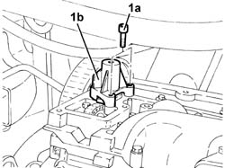
2. Loosen bolts (1a) securing the toothed driven pulley and flange (1b) using tool (1c) for counter-torque.
| Description | Code | Function | |
|---|---|---|---|
| 1c | Counter-torque | Counter-torque for exhaust side camshaft toothed driven pulley |
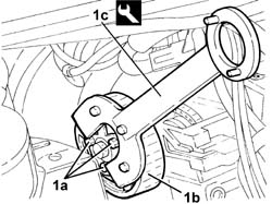
1. Undo bolts (1a) and studs (1b) and remove the single cylinder head extension (1c).
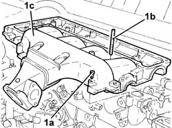
1. Remove camshafts (1a) complete with chain (1b).
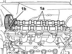
Refitting
1. Position camshafts (1a) complete with chain (1b).
2. Use the 8 mm calibrated pin (2a) for timing the exhaust side camshaft and position THE TIMING REFERENCE (2B) AT THE TOP when timing the inlet side camshaft.
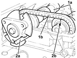
Apply silicone sealant to the mating surface between the cylinder head extension and cylinder head.
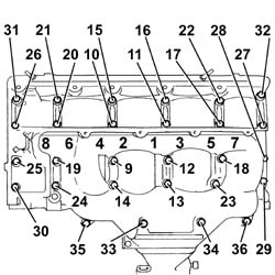
1. Fit the single cylinder head extension and tighten the bolts to the specified torque in the tightening order shown.
references 1 to 8 indicate studs and references 9 to 36 bolts
| Value daNm | Fastening | Component | dia | |
|---|---|---|---|---|
1 1÷8 | Stud | CYLINDER HEAD EXTENSION |
| Value daNm | Fastening | Component | dia | |
|---|---|---|---|---|
0.5 9÷36 | Pretightening, Bolt | CYLINDER HEAD EXTENSION |
| Value daNm | Fastening | Component | dia | |
|---|---|---|---|---|
1 9÷36 | Tightening, Bolt | CYLINDER HEAD EXTENSION |
Position the camshaft drive chain tensioner and tighten the bolts.
1. Position the oil vapour cover/separator in its seat and screw in the bolts. Tighten to the required torque and follow the tightening order indicated.
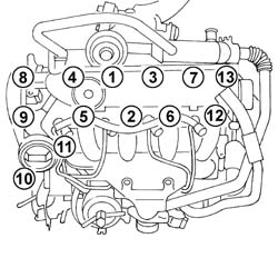
Remove the 8 mm calibrated pin.
Unscrew and remove the exhaust end camshaft flange using a tool for counter-torque.
| Description | Code | Function | |
|---|---|---|---|
| Counter-torque | Counter-torque |
Remove the exhaust camshaft oil seal. This operation is destructive for the oil seal, but take care not to damage the oil seal seat.
1. Fit a new oil seal on the exhaust side camshaft (1a) using a special fitting tool (1b).
| Description | Code | Function | |
|---|---|---|---|
| 1b | Fitting tool | Fit the oil seal on the camshaft |
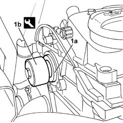
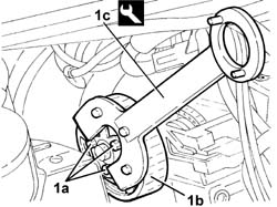
1. Fit flange (1a) into its seat on the exhaust end camshaft and tighten bolt (1b). Tighten to the specified torque using tool (1c) for counter-torque.
| Description | Code | Function | |
|---|---|---|---|
| 1c | Counter-torque | Counter-torque |
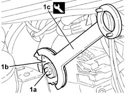
1. Fit toothed driven pulley (1a) into its proper seat on the exhaust end camshaft and tighten bolts (1b). Tighten to the specified torque using tool (1c) for counter-torque.
| Description | Code | Function | |
|---|---|---|---|
| 1c | Counter-torque | Counter-torque for exhaust side camshaft toothed driven pulley |
Fit the injectors in place and tighten the fixing nut checking the torque.
Fit the new rigid fuel supply pipes from the single fuel manifold pipe to the individual injectors and tighten the connectors to the recommended torque.
Place the fuel filter mounting in position and tighten the fixing bolts.
Place the trim in position and tighten the fixing bolts.
Connect the fuel pipe rapid connectors to the filter.
Connect the electrical connection for the fuel filter sensor.
Fit the vacuum pump and tighten the nuts and bolts.
| daNm | Fastening | Component | dia |
|---|---|---|---|
| 2.0 | Bolts | VACUUM UNIT |
| daNm | Fastening | Component | dia |
|---|---|---|---|
| 2.0 | Nut | VACUUM UNIT |
Position the oil vapour recovery fitting and tighten the bolt.
Fit the Swirl valve.
Tighten the bolts and secure the ball joint in its seat.
Fit the oil vapour pipes and renew the retaining bands.
| Description | Code | Function | |
|---|---|---|---|
| Caliper | Open the retaining bands |
See
Op. 1080C54 EXHAUST GAS SUPPLY PIPE FROM E.G.R. VALVE TO INTAKE MANIFOLD - R.R.
Fit the throttle casing in position using the fixing bolts and connect the vacuum pipe to the valve on the throttle casing.
Connect the electrical connection for the heater plug wiring.
Connect the electrical connection for the engine coolant level sensor.
Fit the intake manifold actuator control solenoid and tighten the bolts.
Connect the vacuum pipes to the intake manifold actuator solenoid.
Connect the electrical connections for the injectors.
Connect the electrical connection for the cam angle sensor.
See
Op. 1048A50 TURBOCHARGER AIR INTAKE PIPE - R.R.
See
Op. 1048B22 AIR DELIVERY HOSE FROM HEAT EXCHANGER TO INTAKE MANIFOLD - R + R
See
Op. 1048A10 AIR FILTER ASSEMBLY - R.R.
See
Op. 1032B10 TOOTHED TIMING BELT - R + R FOR TIMING ADJUSTMENT OR REPLACEMENT
See
Op. 1008A46 POWER UNIT RIGID SUPPORT - TIMING SIDE - R.R.
See
Op. 1032D12 TIMING SYSTEM PROTECTIVE COVER(S) - R + R
See
Op. 1092A10 CRANKSHAFT PULLEY - R + R
See
Op. 1024B54 ENGINE FLYWHEEL PROTECTION - R.R
See
Op. 1092G10 SINGLE ENGINE BELT - R.R
See
Op. 1008C10 POWER UNIT UPPER SUPPORT - R R
See
Op. 5050B38 WINDSCREEN WIPER ASSEMBLY - R+R OR REPAIR
See
Op. 7055A18 L/H OR R/H SIDE RUBBING STRIP (ONE) FOR FRONT DOOR - R+R
See
Op. 5050B34 WINDSCREEN WIPER ARM/S COMPLETE WITH BLADE - R+R
Both
See
Op. 5010B18 CLIMATE CONTROL UNIT AIR INTAKE - R.R.
See
Op. 5530B56 BATTERY DRIP TRAY COVER - R.R.
See
Op. 1048B10 RIGID SUPPLY PIPE (ONE) BETWEEN TURBOCHARGER AND HEAT EXCHANGER -R.R.
See
Op. 7055B54 UNDER ENGINE PROTECTION/GUARD - R.R.
See
Op. 7055B91 RIGHT FRONT WHEEL ARCH LINER - R.R.
See
Op. 4450B04 RIGHT FRONT WHEEL - R.R
Check engine fluid levels and top up where necessary.
Parts & tools for this job Staging For 2002 Fiat Ulysse
- PARTEngine gasket setSearch: Fiat Ulysse 2002 engine gasket set
- TOOLTorque wrenchSearch: 3/8 inch torque wrench
- TOOLFeeler gauge setSearch: feeler gauge set
Links open Amazon search results in a new tab. As an Amazon Associate I earn from qualifying purchases.