
Camshaft in cylinder head - r r on vehicle
- Make
- Alfa Romeo
- Model
- GT Factory Service Manual
- Year
- 2003–2010
- Section
- Timing system › Camshaft in cylinder head - r r on vehicle
CAMSHAFT IN CYLINDER HEAD - R R ON VEHICLE
Removing
Position the vehicle on a lift.
PROCEED WITH DRAINING THE HIGH PRESSURE FUEL SYSTEM FOLLOWING THE INSTRUCTIONS GIVEN BELOW.
Start the engine.
Keep the engine idling for 2 minutes.
Detach the fuel pump relay.
Wait until the engine cuts out.
Try and start the enigne: if the engine starts within 10 seconds wait for the engine to cut out, then try and start it again; if the engine does not start within 10 seconds, continue trying for another 5 seconds.
Wait for the engine to cool down.
Make sure that the ignition key is in the OFF position, then disconnect the negative battery terminal.
| Description | Connector | |
|---|---|---|
| Battery | See A1B BATTERY ( BATTERY NEGATIVE ) |
Proceed with the removal
Op. 4450B04 RIGHT FRONT WHEEL R R.
Proceed with the removal
Op. 7055B54 UNDER-ENGINE GUARD - R R.
Proceed with the removal
Op. 1016A40 IGNITION COIL COVER ON CYLINDER HEAD- R+R.
Proceed with the removal
Op. 1032B10 TOOTHED TIMING BELT - R + R FOR TIMING ADJUSTMENT OR REPLACEMENT.
Proceed with the removal
Op. 1032B52 TOOTHED DRIVEN PULLEY (ONE) - R + R
(Inlet side and exhaust side).
Proceed with the removal
Op. 1048A59 PIPE from flow meter to throttle casing hose - R.R..
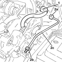
1. Disconnect the rapid connector for the fuel by-pass pipe from the fuel manifold.
Collect the fuel that comes out.
2. Undo the connectors (2a), (2b) and remove the high pressure pipe from the pressure pump to the single fuel manifold (2c).
The high pressure pipe from the pressure pump to the single fuel manifold should be replaced each time it is refitted.
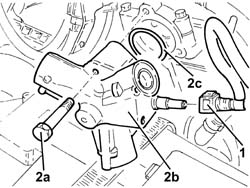
1. Disconnect the rapid connector for the fuel supply pipe from the pressure pump.
2. Undo the bolts (2a) and remove the pressure pump (2b) complete with O-ring (2c).
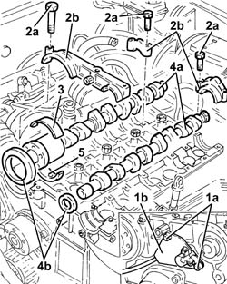
1. Undo the bolts (1a) and move the cam angle sensor (1b).
2. Undo the bolts (2a) and remove the camshaft caps (2b).
The front cap has silicon sealant therefore a plastic hammer should be used for its removal.
3. Remove the inlet side camshaft front supper upper half-bearing.
4. Remove the camshafts (4a) and oil seals (4b).
5. Remove the inlet side camshaft front support lower half-bearing.
Refitting
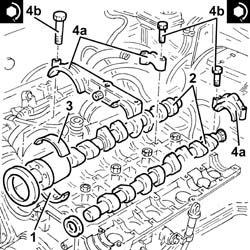
1. Place the inlet side camshaft front support lower half-bearing in its housing.
2. Place the camshafts in their housings.
3. Place the inlet side camshaft front support upper half-bearing in its housing.
4. Place the camshaft caps (4a) in their housings and secure them tightening the bolts (4b) to the recommended torque.
Apply silicon sealant between the front cap and the cylinder head.
| Fastening | Component | Ø | Value (daNm) | |
|---|---|---|---|---|
| 4b | Bolt | CAMSHAFT CAPS | M7 | (Cylinder head side) 1.4 - 1.7 |
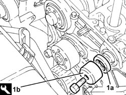
1. Fit the exhaust side camshaft front oil seal (1a) in its housing using the tool (1b).
| Description | Code | |
|---|---|---|
| 1b | Fitting tool | 1.821.228.000 |
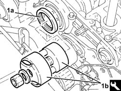
1. Fit the inlet side side camshaft front oil seal (1a) in its housing using the tool (1b).
| Description | Code | |
|---|---|---|
| 1b | Fitting tool | 1.821.252.000 |
Fit the cam angle sensor and secure it using the bolts.
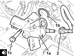
1. Position the pressure pump (1a), complete with O-ring (2b), in its housing and secure it tightening the bolts (1c) to the recommended torque.
| Fastening | Component | Ø | Value (daNm) | |
|---|---|---|---|---|
| 1c | Bolt | HIGH PRESSURE FUEL PUMP | M6 | (Cylinder head side) 0.8 - 1.0 |
2. Connect the rapid connector for the fuel supply pipe from the pressure pump.
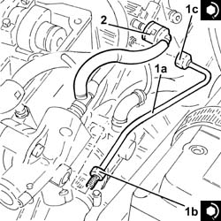
1. Place a new high pressure pipe from the pressure pump to the single fuel manifold pipe (1a) back in its housing and tighten the connectors (1b) and (1c) to the recommended torque.
| Fastening | Component | Ø | Value (daNm) | |
|---|---|---|---|---|
| 1b | Connector | HIGH PRESSURE FUEL PIPE | M10 | (High pressure pump side) 1.6 - 2.0 |
| Fastening | Component | Ø | Value (daNm) | |
|---|---|---|---|---|
| 1c | Connector | HIGH PRESSURE FUEL PIPE | M12 | (Fuel manifold pipe side) 2.0 - 2.4 |
2. Connect the rapid connector for the fuel by-pass pipe to the fuel manifold.
Proceed with the refitting
Op. 1048A59 PIPE from flow meter to throttle casing hose - R.R..
Proceed with the refitting
Op. 1032B52 TOOTHED DRIVEN PULLEY (ONE) - R + R
(Inlet side and exhaust side).
Proceed with the refitting
Op. 1032B10 TOOTHED TIMING BELT - R + R FOR TIMING ADJUSTMENT OR REPLACEMENT.
Proceed with the refitting
Op. 1016A40 IGNITION COIL COVER ON CYLINDER HEAD- R+R.
Proceed with the refitting
Op. 7055B54 UNDER-ENGINE GUARD - R R.
Proceed with the refitting
Op. 4450B04 RIGHT FRONT WHEEL R R.
Connect the negative battery terminal (-).
Remove the vehicle from the lift.
Removing
Position the vehicle on a lift.
Make sure that the ignition key is in the OFF position, then disconnect the negative battery terminal.
| Description | Connector | |
|---|---|---|
| Battery | Vedere A1B BATTERIA ( CABLAGGI ) |
Proceed with the removal
Op. 4450B04 RIGHT FRONT WHEEL R R
Proceed with the removal
Op. 7055B66 ENGINE COMPARTMENT DUST SHIELD PROTECTION IN RIGHT FRONT WHEEL ARCH - R.R.
Proceed with the removal
Op. 1092G10 SINGLE ENGINE BELT R R.
Proceed with the removal
Op. 1092A10 CRANKSHAFT SERVICES PULLEY - R.R..
Proceed with the removal
Op. 1092G20 ENGINE COMPONENT SINGLE BELT FIXED TENSIONER - ONE - R + R.
Proceed with the removal
Op. 1032D12 TIMING SYSTEM PROTECTIVE COVER(S) - R + R.
Proceed with the removal
Op. 1016A40 IGNITION COIL COVER ON CYLINDER HEAD- R+R.
Proceed with the removal
Op. 5510C14 ROCCHETTI/BOBINE DI ACCENSIONE - S.R.
Proceed with the removal
Op. 1016A20 SINGLE CAM COVER - R + R AND REPLACE GASKET.
Proceed with the removal
Op. 1032B10 TOOTHED TIMING BELT - R + R FOR TIMING ADJUSTMENT OR REPLACEMENT.
Proceed with the removal
Op. 1032B52 TOOTHED DRIVEN PULLEY (ONE) - R + R
(Inlet side and exhaust side).
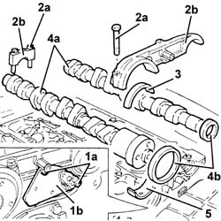
1. Undo the bolts (1a) and move the cam angle sensor (1b).
2. Undo the bolts (2a) and remove the camshaft caps (2b).
3. Remove the inlet side camshaft front supper upper half-bearing.
4. Remove the camshafts (4a) and the front oil seals (4b).
5. Remove the inlet side camshaft front support lower half-bearing.
Refitting
Place the inlet side camshaft front support lower half-bearing in its housing.
Place the camshafts in their housings.
Place the inlet side camshaft front support upper half-bearing in its housing.
Fit the camshaft caps and secure them tightening the bolts to the recommended torque.
Do not fit the 3rd cap for the camshafts because engine timing templates will be fitted in their place.
| Fastening | Component | Ø | Value (daNm) | |
|---|---|---|---|---|
| Bolt | CAMSHAFT CAPS | M7 | (Cylinder head side) 1.4 - 1.7 |
1. Fit the exhaust side camshaft front oil seal (1a) using the tool (1b).
| Description | Code | |
|---|---|---|
| 1b | Fitting tool | 1.821.228.000 |
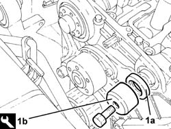
1. Fit the inlet side camshaft front oil seal (1a) using the tool (1b).
| Description | Code | |
|---|---|---|
| 1b | Fitting tool | 1.821.251.000 |
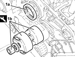
Fit the cam angle sensor and secure it using the bolts.
Proceed with the refitting
Op. 1032B52 TOOTHED DRIVEN PULLEY (ONE) - R + R
(Inlet side and exhaust side).
Proceed with the refitting
Op. 1032B10 TOOTHED TIMING BELT - R + R FOR TIMING ADJUSTMENT OR REPLACEMENT.
Proceed with the refitting
Op. 1016A20 SINGLE CAM COVER - R + R AND REPLACE GASKET.
Proceed with the refitting
Op. 5510C14 ROCCHETTI/BOBINE DI ACCENSIONE - S.R.
Proceed with the refitting
Op. 1016A40 IGNITION COIL COVER ON CYLINDER HEAD- R+R.
Proceed with the refitting
Op. 1032D12 TIMING SYSTEM PROTECTIVE COVER(S) - R + R.
Proceed with the refitting
Op. 1092G20 ENGINE COMPONENT SINGLE BELT FIXED TENSIONER - ONE - R + R.
Proceed with the refitting
Op. 1092A10 CRANKSHAFT SERVICES PULLEY - R.R..
Proceed with the refitting
Op. 1092G10 SINGLE ENGINE BELT R R.
Proceed with the refitting
Op. 7055B66 ENGINE COMPARTMENT DUST SHIELD PROTECTION IN RIGHT FRONT WHEEL ARCH - R.R.
Proceed with the refitting
Op. 4450B04 RIGHT FRONT WHEEL R R
Connect the negative battery terminal (-).
Remove the vehicle from the lift.
Parts & tools for this job Staging For 2003 Alfa Romeo GT
- PARTEngine gasket setSearch: Alfa Romeo GT 2003 engine gasket set
- TOOLTorque wrenchSearch: 3/8 inch torque wrench
- TOOLFeeler gauge setSearch: feeler gauge set
Links open Amazon search results in a new tab. As an Amazon Associate I earn from qualifying purchases.