
System wiring harness on engine r r
- Make
- Alfa Romeo
- Model
- Brera and Spider Factory Service Manual
- Year
- 2005–2010
- Section
- Petrol injection system › System wiring harness on engine r r
SYSTEM WIRING HARNESS ON ENGINE R R
Removing
- Position the vehicle on a lift.
Op. 1072B50 AIR CHAMBER - R.R.
Op. 5530B52 BATTERY SUPPORT/DRIP TRAY - R.R
- Undo the bolts and remove the ignition coil cover.
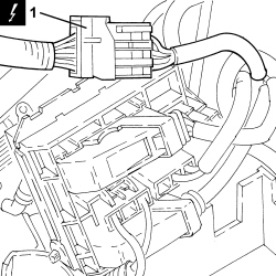
1. Open the junction unit cover and disconnect the electrical connections.
| Description | Connector | |
|---|---|---|
| 1 | Engine compartment junction unit | See B001 JUNCTION UNIT |
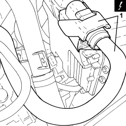
1. Disconnect the electrical connection from the electronic injection system control unit.
| Description | Connector | |
|---|---|---|
| 1 | Engine management control unit | See M010 ENGINE MANAGEMENT ECU |
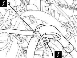
1. Disconnect the electrical connection from the fuel pressure regulator on the air intake/fuel manifold duct.
| Description | Connector | |
|---|---|---|
| 1 | Fuel pressure regulator | See N077 FUEL PRESSURE REGULATOR |
2. Disconnect the electrical connection from the fuel pressure sensor.
| Description | Connector | |
|---|---|---|
| 2 | Fuel pressure sensor | See K083 FUEL PRESSURE SENSOR |
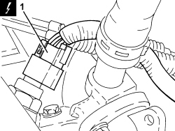
1. Disconnect the electrical connection from the engine coolant temperature sensor.
| Description | Connector | |
|---|---|---|
| 1 | Engine coolant temperature sensor/sender unit | See K036 ENGINE COOLANT TEMPERATURE SENSOR/SENDER UNIT |
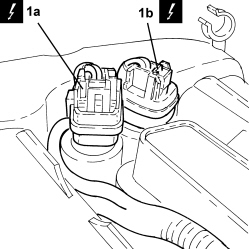
1. Disconnect the electrical connections (1a) and (1b) from the phase transformer electromagnets.
| Description | Connector | |
|---|---|---|
| 1a | Exhaust side phase transformer solenoid valve | See N093 PHASE SHIFTER SOLENOID VALVE ON EXHAUST SIDE |
| Description | Connector | |
|---|---|---|
| 1b | Inlet side phase transformer solenoid valve | See N092 PHASE SHIFTER SOLENOID VALVE ON INTAKE SIDE |
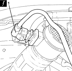
1. Disconnect the electrical connection from the air flow meter.
| Description | Connector | |
|---|---|---|
| 1 | Air flow meter | See K041 AIR FLOW METER |
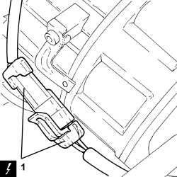
1. Disconnect the electrical connection of the air conditioner compressor.
| Description | Connector | |
|---|---|---|
| 1 | Air conditioning compressor engagement electro-magnet | See L020 AIR CONDITIONING COMPRESSOR ENGAGEMENT ELECTRO-MAGNET |
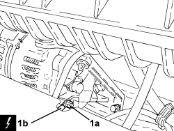
1. Undo the nut (1a) and disconnect the earth lead (1b) from the alternator.
| Description | Connector | |
|---|---|---|
| 1b | Alternator | See A010 ALTERNATOR |
1. Disconnect the electrical connection from the engine oil pressure warning light switch.
| Description | Connector | |
|---|---|---|
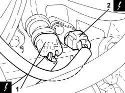
| 1 | Insufficient engine oil pressure sensor (switch) | See K030 LOW ENGINE OIL PRESSURE SENSOR (SWITCH) |
2. Disconnect the electrical connection from the engine rpm sensor.
| Description | Connector | |
|---|---|---|
| 2 | Engine rpm sensor | See K046 RPM SENSOR |
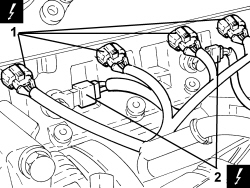
1. Disconnect the electrical connections from the injectors.
| Description | Connector | |
|---|---|---|
| 1 | Injector | See N070 INJECTOR |
2. Disconnect the electrical connection for the detonation sensor.
| Description | Connector | |
|---|---|---|
| 2 | Detonation sensor - 2 | See K050 DETONATION SENSOR |
- Release the system cable loom from the fastenings and remove it.
Refitting
- Place the system cable loom in its housing and secure it.
- Connect the electrical connection for the detonation sensor.
- Connect the electrical connections to the injectors.
- Connect the electrical connection for the engine rpm sensor.
- Connect the electrical connection to the engine oil pressure warning light switch.
- Connect the earth lead to the alternator and tighten the nut.
- Connect the electrical connection to the air conditioning compressor.
- Connect the electrical connection to the air flow meter.
- Connect the electrical connections to the phase transformer electromagnets.
- Connect the electrical connection to the engine coolant temperature sensor.
- Connect the electrical connection to the fuel pressure sensor.
- Connect the electrical connection to the fuel pressure regulator on the air intake/fuel manifold duct.
- Connect the electrical connections to the electronic power module.
- Connect the electrical connections to the cam angle sensors.
- Connect the electrical connection to the electronic injection system control unit.
- Connect the electrical connections and close the junction unit cover.
- Place the ignition coil cover back in its housing and tighten the bolts.
Op. 5530B52 BATTERY SUPPORT/DRIP TRAY - R.R
Op. 1072B50 AIR CHAMBER - R.R.
- Remove the vehicle from the lift.
This operation can only be carried out with the power unit removed, therefore refer to:
Op. 1004B10 POWER UNIT WITH MANUAL GEARBOX - R.R
Op. 1004D10 POWER UNIT (MANUAL GEARBOX), REMOVED, DISMANTLE AND REASSEMBLE
Parts & tools for this job Staging For 2005 Alfa Romeo Brera
- PARTEngine gasket setSearch: Alfa Romeo Brera 2005 engine gasket set
- TOOLTorque wrenchSearch: 3/8 inch torque wrench
- TOOLFeeler gauge setSearch: feeler gauge set
Links open Amazon search results in a new tab. As an Amazon Associate I earn from qualifying purchases.