
Air chamber - r.r.
- Make
- Alfa Romeo
- Model
- Brera and Spider Factory Service Manual
- Year
- 2005–2010
- Section
- Inlet and exhaust manifolds › Air chamber - r.r.
AIR CHAMBER - R.R.
Removing
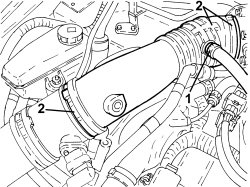
1. Loosen the band and disconnect the engine oil vapour pipe, left head, from the intake chamber air inlet pipe.
2. Loosen the bands and remove the intake chamber air intake pipe.
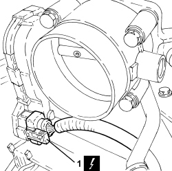
1. Disconnect the electrical connection for the throttle casing.
| Description | Connector | |
|---|---|---|
| 1 | Integrated throttle casing actuator | See N075 THROTTLE BODY ACTUATOR |
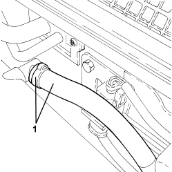
1. Loosen the band and disconnect the brake servo vacuum intake pipe from the intake chamber.
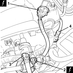
1. Disconnect the electrical connection for the air pressure sensor.
| Description | Connector | |
|---|---|---|
| 1 | Absolute pressure sensor | See K048 ABSOLUTE PRESSURE SENSOR |
2. Disconnect the electrical connection of the fuel vapour flow enablement solenoid valve.
| Description | Connector | |
|---|---|---|
| 2 | Fuel vapour recovery solenoid valve | See L10 FUEL VAPOUR RECOVERY SOLENOID VALVE |
3. Disconnect the rapid connector for the fuel vapour pipe, solenoid valve side.
4. Disconnect the rapid connector for the engine oil vapour pipe, right head, tappet cover side.
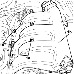
1. Undo the bolts (1a) and remove the intake chamber (1b).
Refitting
- Fit the intake chamber in place and secure it using the bolts.
| Component | Fastening | dia | Value (daNm) | Validity |
|---|---|---|---|---|
| Air chamber | Bolt | 2.3 | 3.2 JTS |
- Connect the rapid connector for the engine oil vapour pipe, right head, tappet cover side.
- Connect the rapid connector for the fuel vapour pipe, solenoid valve side.
- Connect the electrical connection for the fuel vapour flow enablement solenoid valve.
- Connect the electrical connection for the air pressure sensor.
- Connect the brake servo vacuum intake pipe to the intake chamber and secure it using the band.
- Connect the electrical connection for the throttle casing.
- Place the intake chamber air inlet pipe in position and secure it using the bands.
- Connect the engine oil vapour pipe, left head, to the intake chamber air inlet pipe and secure it using the band.
Removing
- Make sure that the ignition key is in the OFF position, then disconnect the battery terminal (-).
| Description | Connector | |
|---|---|---|
| Battery | See A001 BATTERY |
Op. 1048A34 SLEEVE(S) FROM FLOW METER TO AIR SUPPLY CAPACITY CASE - R + R
Op. 1056F17 THROTTLE BODY WITH DVL R R
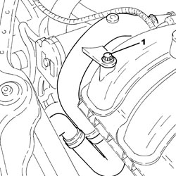
1. Undo the bolt fixing the lower coolant outlet hose from the radiator, air chamber side.
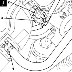
1. Loosen the band and disconnect the brake servo vacuum intake pipe, air chamber side.
2. Disconnect the electrical connection from the fuel vapour solenoid valve.
| Description | Connector | |
|---|---|---|
| 2 | Fuel vapour recovery solenoid valve | See L010 FUEL VAPOUR RECOVERY SOLENOID VALVE |
3. Disconnect the rapid connector for the fuel vapour pipe from the fuel vapour solenoid valve.
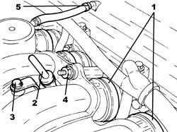
1. Loosen the bands fixing the air chamber to the hoses.
2. Release the engine oil dipstick and remove it.
3. Undo the bolt securing the engine oil dipstick tube to the air chamber.
4. Undo the nut fixing the air chamber to the intake manifold.
5. Loosen the band and disconnect the engine oil vapour recovery pipe from the tappet cover.
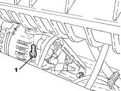
1. Undo the bolt fixing the mounting bracket to the air chamber.
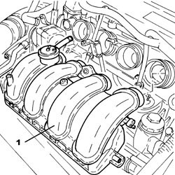
1. Remove the air chamber.
Refitting
- Place the air chamber back in its housing.
- Tighten the bolt fixing the mounting bracket to the air chamber.
- Connect the engine oil vapour recovery pipe to the tappet cover and tighten the band.
- Tighten the nut fixing the air chamber to the intake manifold.
- Tighten the bolt securing the engine oil dipstick tube to the air chamber.
- Place the engine oil dipstick back in its housing.
- Tighten the bands fixing the air chamber to the hoses.
- Connect the rapid connector for the fuel vapour pipe to the fuel vapour solenoid valve.
- Connect the electrical connection to the fuel vapour solenoid valve.
- Connect the brake servo vacuum intake pipe, air chamber side and tighten the band.
- Tighten the bolt fixing the lower coolant outlet hose from the radiator, air chamber side.
Op. 1056F17 THROTTLE BODY WITH DVL R R
Op. 1048A34 SLEEVE(S) FROM FLOW METER TO AIR SUPPLY CAPACITY CASE - R + R
- Connect the negative battery terminal.
Parts & tools for this job Staging For 2005 Alfa Romeo Brera
- PARTExhaust gasketSearch: Alfa Romeo Brera 2005 exhaust gasket
- TOOLPenetrating oilSearch: penetrating oil
- TOOLOBD2 scannerSearch: OBD2 scanner
Links open Amazon search results in a new tab. As an Amazon Associate I earn from qualifying purchases.