
Air conditioning casing and components
- Make
- Alfa Romeo
- Model
- Brera and Spider Factory Service Manual
- Year
- 2005–2010
- Section
- General › Air conditioning casing and components
AIR CONDITIONING CASING AND COMPONENTS
INTRODUCTION
The climate control system makes it possible to alter the features of the air introduced into the passenger compartment (temperature, humidity) designed to create and maintain a high level of comfort whilst driving.
Climate control system components
The climate control system components are illustrated in the diagram.
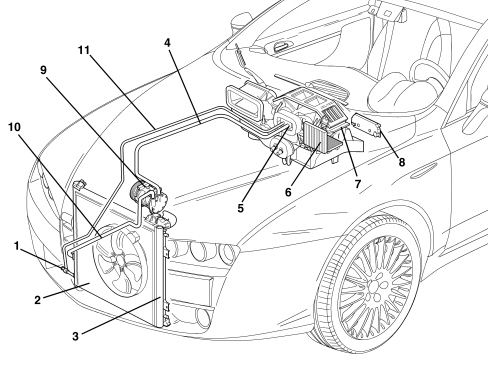
1. Linear pressure switch
2. Condenser
3. Drier filter built into the condenser
4. Low pressure gas pipe
5. Expansion valve
6. Evaporator
7. Dect/distributor assembly
8. Control panel with electronic control unit
9. Compressor
10. High pressure gas pipe
11. High pressure fluid pipe
Operating principle
The aim of refrigeration equipment is to absorb heat from an environment. In order to do this an air conditioner has recourse to certain fluids (known as refrigerants) capable of cooling down (lowering their temperature) and changing state (from liquid to gas) when they are subject to a large drop in pressure, expanding. They are therefore capable of absorbing heat from the environment. When the temperature increases thereby also increasing the pressure, they change state, another time, from gas to liquid, and condense.
The first problem is therefore to liquefy this gas which can be achieved simply by bringing it to a temperature below that of evaporation (or boiling) which, as has already been stated, is -26°C at atmospheric pressure for R134a.
In order for this to be achieved at ambient temperature which, in our case, may be rather high (in the engine compartment), it is necessary to increase the evaporation point of the gas so that it remains liquid until the moment it is made to expand to produce the desired refrigerant effect.
To raise the boiling point of the gas its pressure must be increased, at the same time, decreasing the temperature.
In order for this to take place the system requires a certain amount of power. This power, supplied by the compressor, is subtracted from the power produced by the engine.
The operating principle of the refrigerant cycle phases in the air conditioning system for a motor vehicle can be summed up as follows.
The gaseous R134a refrigerant is drawn in by the compressor at a pressure of between 0.5 and 2 bar and is compressed at a value of between 10 and 17 bar. The boiling point at these pressures is around 60 °C.
This fluid, heated by the compression stage at 80 - 100 °C, always in a gaseous state, in the compressor where, through the effect of the cooling air flow (produced by the vehicle moving forward or through the action of the fan) that passes through, reaches condensation point, changing at high pressure to a liquid state.
Later on the refrigerant passes through a filter which has three functions: to trap the impurities, absorb the dampness contained in the circuit and work as a reserve reservoir for the actual refrigerant.
The refrigerant reaches the expansion valve, where it is introduced into the evaporator where the pressure is around 1.5 atm. (1.52 bar). At this pressure the liquid/vapour system saturated with the refrigerant fluid is in equilibrium at a temperature of about -7 °C. At the same time, the air that passes through the evaporator (through the action of a fan), being at a considerably higher temperature than the refrigerant fluid it contains, causes it to boil and evaporate completely by imparting heat. On cooling, the air deposits some of the dampness it contains on the evaporator fins in the form of droplets which are collected in a chamber and drained off from the vehicle.
The cooled and dehumidified air is sent inside the vehicle. The refrigerant is drawn in by the compressor again at the evaporator outlet, thereby giving rise to a new cycle once again.
The route of the refrigerant fluid can be summarized as follows:
- In the compressor - the fluid coming from the evaporator is gaseous (temp. -5, -7°C, pressure 0.5 - 2 bar). Compression phase - the gaseous fluid is overheated (temp. 80 -100 °C, pressure 10 -17 bar).
- Condensator - Compression phase: the fluid gives off heat to the outside, cools down and returns to a liquid state (temp. 40 -60°C, pressure 10 -17 bar).
- Thermostatic expansion valve - Expansion phse - the fluid loses pressure (0.5 - 2 bar, possibly even 3 bar) becomes a gas + liquid mixture; the temperature is low, typical of air conditioning.
- Evaporator - Evaporation phase - the fluid becomes completely gaseous because the hot air driven by the fan finds itself at a higher temperature than the refrigerant fluid and causes it to boil and evaporate completely giving off heat. The temperature is low, typical of air conditioning (pressure 0.5 - 2 bar).
Types of system
This vehicle can be equipped with different climate control systems for the passenger compartment:
- manual climate control
- dual zone automatic climate control
Manual climate control: the user sets the air temperature, distribution and flow rate and they remain like that until they are altered by the user later on.
Automatic climate control (dual zone): the user can set the parameters and select automatic system management. If they so wish, the user can preseve the facility to manage the system manually.
In addition, the automatic climate control system on this vehicle is the dual zone type (driver''s zone and front passenger zone), in other words the system has dual controls for the driver and the passenger and is capable of managing the settings for the two users separately, varying the air temperature and distribution parameters (the flow rate cannot be different in the zones) with a certain degree of independence.
MANUAL CLIMATE CONTROL
The manual climate control system control panel is illustrated in the diagram below.
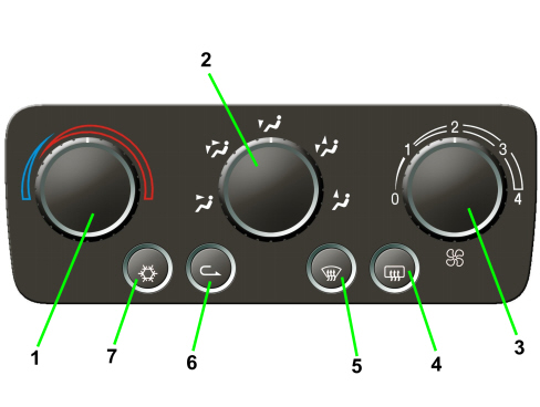
1. Air temperature adjustment knob
2. Passenger compartment air distribution selection knob
3. Fan speed selection knob
4. Heated rear windscreen and exterior rear view mirror defrosting on/off button
5. MAX DEF function on/off button (defrosting/demisting of windscreen, front windows and exterior rear view mirrors)
6. Interior air recirculation on/off button
7. Climate control compressor on/off button
The manually operated climate control system is managed by an electronic controlunit, known as the Climate Control Node (NCL) connected to the vehicle electrical system B-CAN and incorporated in the climate control system control panel in the middle of the dashboard.
The control unit pin out is summarized in the table below.
| Pin | Signal |
|---|---|
| 1 | earth |
| 2 | direct power supply (from F39) |
| 3 | n.c. |
| 4 | n.c. |
| 5 | n.c. |
| 6 | n.c. |
| 7 | n.c. |
| 8 | additional heater control signal PTC1 |
| 9 | additional heater control signal PTC2 |
| 10 | fan relay feed |
| 11 | compressor engagement positive (output) signal |
| 12 | B-Can A line |
| 13 | B-Can B line |
| 14 | recirculation actuator control |
| 15 | recirculation actuator control |
| 16 | recirculation actuator control |
| 17 | recirculation actuator control |
| 18 | n.c. |
| 19 | distribution actuator control |
| 20 | distribution actuator control |
| 21 | distribution actuator control |
| 22 | distribution actuator control |
| 23 | mixture actuator control |
| 24 | mixture actuator control |
| 25 | mixture actuator control |
| 26 | mixture actuator control |
Operating strategy
The manual air conditioning also allows the user to manage the temperature and the intake of air into the passenger compartment using the control knobs and buttons.
The following parameters/functions can be altered manually:
- Temperature
- Distribution in 5 positions
- Fan speed.
- Compressor enablement
- Defrosting/demisting function
- Recirculation
The transmission of the air mixing, air distribution and recirculation commands from the knobs to the climate control casing takes place by means of electric motors.
The compressor can only be activated if one of the fan speeds is switched on.
AUTOMATIC CLIMATE CONTROL
The automatic climate control system is managed by a control unit which is capable, thanks to an extremely sophisticated operating logic, of controlling the temperature in two zones of the passenger compartment heating or cooling the air to produce the desired comfort level.
The climate control system automatically adjusts the following parameters/functions:
- Air temperature at the driver''s/passenger side vents
- Fan speed (continuous variation)
- Driver/passenger side air distribution
- Engagement of compressor
- Recirculation
Controls
The user interface for this control unit has the following layout.
Dual/triple zone front controls
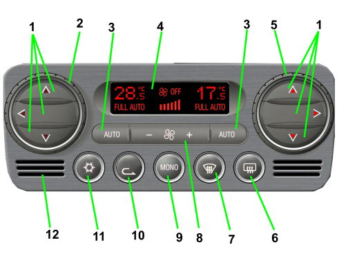
1. Air distribution selection buttons (driver side and passenger side)
2. Driver''s temperature adjustment knob
3. AUTO function activation button (automatic operation)
4. Climate control system information display
5. Passenger side temperature adjustment knob
6. Heated rear windscreen on/off button
7. MAX DEF function activation button (rapid defrosting/demisting of front windows, heated rear windscreen and exterior rear view mirrors)
8. Fan speed increase/decrease buttons
9. MONO function activation button (temperature setting alignment)
10. Interior air recirculation on/off button
11. Climate control compressor on/off button
12. Interior air temperature sensor
Main specifications
The following parameters/functions can be set/altered manually:
- Temperature requested
- Fan speed
- Distribution in 7 positions
- Compressor enabling/disabling
- Defrosting/demisting function
- Recirculation
- Single zone function
Manual selections always take priority over automatic ones, except those related to the safety of the vehicle, and are memorized until the user switches back to automatic operation.
The manual setting of a function does not adeversely affect the control of the others set automatically, in particular the control of the temperature is always automatic when the system is working with the exception of situations in which the manual selections adversely affect the possibility of controlling/maintaining the required temperature; in this case the temperatures shown on the display flash indicating that the temperature is no longer under the control of the automatic system.
Each time it is switched on (Key on) the system restores the conditions memorized when it was switched off, with the exception of the MAX-DEF function which is zeroed.
There is a facility for switching the system off manually (OFF) using the fan button until 0 bars are selected for the flow rate, completely deactivating the air conditioning system (except for Recirculation and Heated Rear Windscreen) and isolating the passenger compartment from the outside environment.
The MAX-DEF function groups together a collection of actions that make it possible to quickly demist the windscreen, the side windows, the heataed rear windscreen and the exterior rear view mirrors.
Climate control system control unit
The climate control system is managed automatically by an electronic control unit known as the Climate Control Node (NCL) which is charged with keeping the air climate control conditions set, and therefore desired, by the user (or users) unchanged.
The NCL is connected to the vehicle''s electrical system B-CAN.
The NCL is incorporated in the climate control system control panel fitted in the dashboard in the middle. The diagram illustrates the back of the control unit showing the connections to the electrical system and the connector pin out.
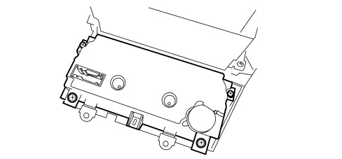
| Pin | Signal |
|---|---|
| 1 | earth |
| 2 | direct power supply (from F39) |
| 3 | actuator positive power supply |
| 4 | fan adjuster positive power supply |
| 5 | earth for evaporation sensor |
| 6 | solar sensor power supply |
| 7 | additional heater control signal PTC1 |
| 8 | actuator BUS communication line |
| 9 | additional heater control signal PTC2 |
| 10 | B-Can A line |
| 11 | B-Can B line |
| 12 | n.c. |
| 13 | signal from evaporator sensor |
| 14 | n.c. |
| 15 | compressor engagement positive (output) signal |
| 16 | n.c. |
| 17 | fan regulator PWM control signal |
| 18 | n.c. |
| 19 | signal from pollution sensor |
| 20 | signal from demisting sensor |
| 21 | n.c. |
| 22 | left solar sensor signal |
| 23 | n.c. |
| 24 | right solar sensor signal |
| 25 | n.c. |
| 26 | fan regulator feedback signal |
Some of the CAN nodes, including the climate control system control unit, are programmed with default settings that the customer will find when they purchase the vehicle. If the control unit is being replaced, the Parts Dept. will send a pristine component: once fitted, the data memorized in the Body Computer must be transferred to it by carrying out the "PROXI ALIGNMENT" procedure using the Examiner.
The various actuators in the climate control system unit, even if similar, are specifically programmed and are not interchangeable.
Operating strategy
The principle on which the temperature control is based is linked to the "EQUIVALENT TEMPERATURE" concept.
A control based on the equivalent temperature concept does not try and keep the passenger compartment at a constant temperature, but tries to maintain the user''s feeling of heat.
The thermal sensation depends on all the thermal energy exchanges with the environment and is estimated by the climate control system control unit on the basis of ambient parameters.
In particular, inside a VEHICLE, it depends on the following:
- Average temperature in the passenger compartment
- Temperature of the air sent to the passenger compartment interior
- Temperature of the walls and surfaces exposed to passengers (dashboard, seats, etc.)
- Air flow rate in the passenger compartment
- Sun''s rays
There is a sensor to measure the sun''s rays, which acquires a bilateral signal (left-right) which contributes towards determining the comfort conditions in terms of air distribution and temperature.
The only action that the user has to take is to identify and select an equivalent temperature value that is comfortable for them and, irrespective of outside conditions, the system will work to adjust all the variables under its control to ensure the desired thermal sensation.
The system automatically adjusts the following parameters/functions:
- air temperature at the vents
- air distribution
- air flow rate in the passenger compartment
- compressor enablement
- recirculation
All these functions can be modified manually, in other words the user can intervene and select one or more functions at will: in this way the user removes the control of the functions selected manually from the automatic system (with the system unable to intervene unless it is for safety reasons) to guarantee the requested equivalent temperature.
Air mixture control
The control of the outlet air temperature at the vents is fairly important in the adaptation of the Equivalent Temperature to the value set with reference to comfort conditions.
This check is carried out by activating the mixture flap.
The movement of the mixture actuator is filtered so that movements that are too quick cannot take place thereby preventing unpleasant fluctuations in temperature.
Air flow rate control
Another fundamental parameter for reaching and maintaing the Equivalent Temperature at the value set is the control of the outlet air flow rate at the vents. This check is carried out by activating the fan speed control.
For this purpose the control algorithm calculates a flow rate figure dependent on the previous flow rate and the difference between the objective equivalent temperature and the one measured.
Similarly to the calculation of the Mixture, in this case too the value of the flow rate is filtered so that variations that are too rapid are not produced; a "seasonal" parameter is also taken into consideration to adapt the operation of the fan depending on whether it is summer or winter.
Use of the system
As described previously, the climate control system control system is based on the equivalent temperature and works to stabilize the thermal sensation inside the passenger compartment (compensating for any variation in the outside climate conditions).
The user has to identify and select an equivalent temperature value that they are comfortable with and, irrespective of outside conditions (it does not matter whether it is summer or winter, sunny or raining), the system will work, adjusting all the variables in its power to ensure the desired thermal sensation.
- To check that the system control is fully prepared for automatic operation, make sure that the words FULL AUTO are shown on the display.
To produce the fully automatic conditions, press the AUTO buttons which enable the automatic adjustment functions: DISTRIBUTION, AIR FLOW RATE, COMPRESSOR ENABLEMENT, RECIRCULATION MANAGEMENT.
If the air flow rate or distribution is selected manually, the word FULL will disappear; if the compressor is disabled manually the LED will go out: if the system is capable, depending on the ambient temperature, of keeping the comfort level constant, the word AUTO will remain on, otherwise it will go out.
- The compressor button enables the COMPRESSOR ON/OFF function When the compressor is working, the user is guaranteed not only the possibility of cooling the temperature of the passenger compartment (especially in hot weather), but also the chance of dehumidifying the air (preventing the problem of the windows misting up, especially in cold weather).
The compressor, however, cannot work when the outside temperature is low. In this case, to prevent problems of misting up, the system forces the dynamic air intake leaving the button enabled (this way the user can set it how they want).
In any case, if there visibility problems linked to the windscreen misting up, it is a good idea to check that the recirculation button LED is off.
The recirculation button can be managed manually or automatically. Automatic management of the recirculation is also connected (if present) to the air quality sensor (AQS) which, on recognizing the pollutant factors present inthe air, closes the recirculation automatically.
If there is no AQS, the automatic management of the recirculation is carried out with a view to improving the thermal adjustment transitions.
The exchange of air inside the passenger compartment is also guaranteed (every 25 minutes consecutively with the recirculation on, the system moves automatically to outside air for a period of 60 seconds).
When the AQS sensor is present, it is disabled automatically at low outside temperatures to prevent the windscreen from misting up. The user, using the rolling recirculation button, can, on exiting from the fully automatic function, re-enable the operation of the AQS sensor.
The information transmitted by the AQS is compared by the system with the information from the (optional) DEFOG sensor (which controls the degree of humidity present on the windscreen). If the windscreen is misted up and the compressor is disabled, the system forces the recirculation open for safety reasons (the priority of the system is obviously to ensure good visibility for the driver).
To switch the system off, keep the speed rocker switch pressed at the "-" symbol until the word OFF appears on the display.
When the system is OFF, the passenger compartment is insulated from the outside (recirculation closed, LED in the button on). The recirculation can, however, be opened (to allow outside air to enter the passenger compartment) by pressing the recirculation button (switching off the LED).
The system contains pre-defined functions that determine specific operation in certain conditions.
- LO function. When a temperature of less than 16°C is set, the "maximum cooling" condition is produced; in these circumstances the system is in MONO operation, the words FULL and AUTO go out and the following actions are activated: temperature regulator in maximum cold position, front air distribution, air flow rate at seasonal maximum, compressor enablement, recirculation as requested by user.
- HI function. When a temperature of more than 32°C is set, the "maximum heating" condition is produced; in these circumstances the system is in MONO operation, the words FULL and AUTO go out and the following actions are activated: temperature regulator in maximum hot position, air distribution to feet, air flow rate at seasonal maximum, compressor managed according to logic (depending on whether rest is more than 2°C), recirculation as requested by user.
- MAX DEF function. When the specific button (7) is pressed, the system switches to MONO, the words FULL and AUTO go out and the following actions are implemented: temperature regulator in maximum hot position, air distribution to the windscreen, increase in the air flow rate (if the temperature of the engine is sufficiently high), compressor function enabled (LED on), recirculation forced open, HEATED REAR WINDSCREEN activated (LED on).
Functions
Temperature setting control knob
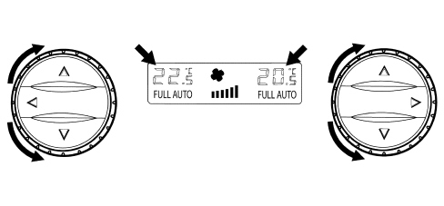
Knob for setting passenger compartment temperature (zone by zone).
By turning the knob for the desired zone (driver/passengers) the desired passenger compartment temperature can be increased (clockwise direction) or decreased (anti-clockwise direction).
The increases/decreases are in steps of 0.5 ºC and one complete revolution of the knob produces 24 steps.
The temperature settings are memorized at the key off and then restored at the next key on.
The temperature range can be set between 16 and 32 ºC; below 16 ºC the value set becomes «LO» whilst above 32 ºC the value set becomes «HI».
If the user sets a temperature below the outside temperature, with the compressor button disabled, the system is not capable of reaching it or maintaining it and this impossibility is signalled by the Temperature setting flashing.
Hi condition
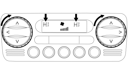
The HI condition is reached by setting a temperature above 32 ºC.
This request by the user switches off the words FULL and AUTO, forces the system to MONO and involves the following actions:
- Mixer in fully hot position.
- Distribution towards the feet.
- Air flow rate increase (if the temperature of the engine is sufficiently high).
- Recirculation remains as requested by user.
Manual settings are allowed in the HI condition.
Exiting the MONO condition using the button determines exiting the HI function and the temperature setting of 32° C for both zones.
If the driver turns the temperature setting this moves the passenger setting out of HI to 32° C
If the passenger turns the temperature setting this also moves the driver''s setting out of HI (to 32ºC), then changing their own settings placing the system in the 2/3 zone mode.
Lo condition
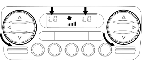
The LO condition is reached by setting a temperature below 16 ºC.
This request by the user switches off the words FULL and AUTO, forces the system to MONO and involves the following actions:
- Mixer in max cold position.
- Air distribution to the dashboard
- Air flow rate increase
- Compressor enablement
Manual settings are allowed in the LO condition.
Exiting the MONO condition using the button determines exiting the LO function and the temperature setting of 16° C for both zones.
If the driver turns the temperature setting this moves the passenger setting out of LO to 16° C
If the passenger turns the temperature setting this also moves the driver''s setting out of LO (to 16ºC), then changing their own settings placing the system in the Dual Zone mode.
The flashing logic is valid, if the compressor is disabled after the LO request and the forced recirculation is automatic if it was not already.
Auto button
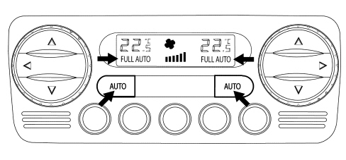
Pressing this button restores the automatic operation of the following functions
- Air distribution
- Fan speed
- Compressor
- Recirculation
The words FULL AUTO lit up indicate that all the above mentioned functions are controlled automatically.
The word FULL goes out in the area considered when a Distribution manoeuvre is carried out manually.
The word FULL goes out in all the zones when a manual operation is carried out on the flow rate, compressor or recirculation.
The word AUTO also goes out if the control system (mainly when the compressor is manually disabled) does not reach or maintain the required temperature.
The button that disables the Compressor does not switch off the word AUTO when the system is capable of maintaining the desired comfort.
Distribution buttons
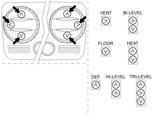
There are 7 possible positions for the air distribution (VENT, BI-LEVEL, HEAT, FLOOR, DEF, HI-LEVEL, TRI-LEVEL).
In Automatic mode the system manages the distribution and does not display its selection.
One of the 7 positions can be selected manually by activating the buttons according to the following combination logic:
- Main Distributions:
DEF
VENT
FLOOR
- Combined Distributions
BI-LEVEL
HEAT
HI-LEVEL
TRI-LEVEL
With the combined distribution activated, the LED goes out when one of the two buttons is pressed.
With the main distribution activated (one LED on), when the same button is pressed the existing distribution is confirmed.
Recirculation
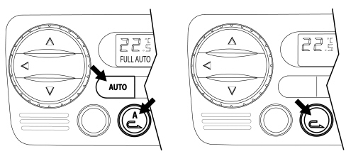
The recirculation button operates with a ROLLING logic.
By pressing the AUTO button, automatic management of the recirculation is selected
- Automatic
The A in the button lights up
This informs the user that the recirculation is managed automatically to improve the thermodynamic comfort; in addition, if an AQS sensor is fitted, it is also dependent on the quality of the air.
For safety reasons (e.g. windows misted up, long periods of closure), A is switched off to signal the deactivation of the automatic control.
When A is switched off, it is possible to select automatic operation using the recirculation rolling button and exiting from the system fully automatic mode.
- Recirculation forced closed
With this type of manual operation, the red LED signals the closure of the recirculation flap.
- Recirculation forced open (outside air)
With this type of manual operation, the red LED off signals the forced opening of the outside air flap.
This mode should be selected if the windows are misted up.
Air flow rate variation control
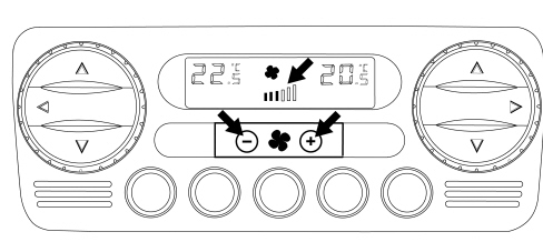
The air flow rate can be adjusted manually in steps, which are displayed as one bar for every 2 steps up to a maximum of 6 bars when it then goes out.
If there have been no manual interventions, the fan speed is controlled continuously by the system and this is shown on the display by the relevant number of bars lighting up according to the flow rate.
If the ventilation control is operated manually, the FULL AUTO condition is exited. In particular, to increase or decrease the fan speed, press the rocker switch on the + and - symbols.
At the key on, if the control unit is controlling the air flow rate Automatically, this air flow rate corresponds to the 1st bar (minimum flow rate) until the engine is started.
If the compressor is disabled, the ventilation control can be operated manually until the display shows 0 bar.
If the compressor is enabled and the engine started, the manual ventilation cannot go below 1 bar on the display because with the compressor enabled there must be a minimum air flow rate to prevent ice from forming in the evaporator.
Switching off the control unit (off)
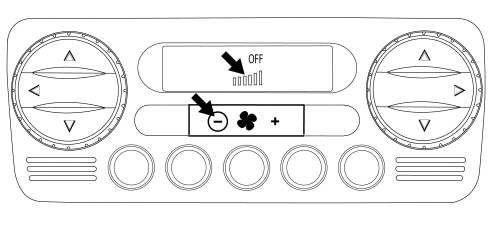
Operating the air flow rate control (decrease) below 0 bars (fan off) causes the word OFF only to light up on the display.
The following actions take place in OFF:
- memorizing of the current state
- switching off of the display (with the exception of the OFF symbol)
- closed recirculation and relevant LED lit up
- compressor excluded
- fan excluded
- mixer in max cold position
- distribution in Vent
- in the OFF state the Heated Rear Windscreen button is managed normally without activating the climate control system.
In the OFF condition the recirculation button is dual control (ON/OFF) opening (red LED off) and closing (red LED on) the flap, without managing the automatic operation (red LED off).
Pressing the air flow rate control button at the + symbol or pressing any button (except for the Heated Rear Windscreen and Recirculation) or pressing any of the AUOT buttons, switches the system back on.
When exiting from OFF, the recirculation returns to Automatic mode.
Compressor enablement
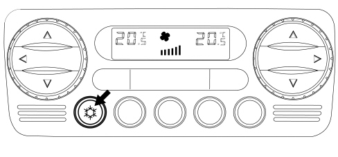
With the compressor enablement LED on, pressing the button switches the LED off and disables the compressor
Once the button has been pressed, this selection remains memorized indefinitely even after the vehicle has been switched off, the same as for the other manual controls.
The button is dual function: pressing it a second time re-enables the compressor and switches the LED on.
With the compressor disabled, the system checks whether the outside temperature is higher or lower than/the same as the temperature set:
- if the outside temperature is less than the temperature set then the system works normally and is capable of complying with the request even without the compressor being switched on;
- of the outside temperature is higher than the temperature set then the system is not capable of complying with the request and signals this by making the temperature settings flash.
The control (system with compressor disabled and outside temperature higher than temperature set) is activated at the key on.
Mono
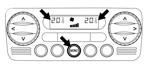
Pressing the MONO button determines the following action:
- the temperature set by the passenger made is made the same as that set by the driver and the LED comes on.
From that moment the system behaves like a single zone system.
Pressing the MONO button again or altering the temperature set by the passenger causes the following results:
- the MONO button LED goes out and there is a shift to dual zone temperature control.
Max def
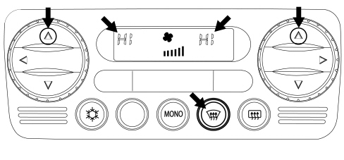
The Max-Def function is also managed with the engine switched off.
The following operations are activated:
- Max-Def LED lit up
- memorizing of the function state and previous displays of Max-Def control
- words FULL and AUTO switched off and automatic recirculation (if on)
- switching on of the DEF distribution, compressor enablement, MONO and HEATED REAR WINDSCREEN LEDs
- display of fully hot temperature (HI)
- display of the ventilation in the front display
- switching off of the rear panel
- activation of the following controls
- air flow rate increase (with coolant temperature sufficiently hot)
- air distribution in Def position (before implementing the mix)
- forced air intake open (dynamic)
- compressor function enabled
- AQS disabled (if present)
- rear windscreen defrosting
When exiting from Max-Def the mix is implemented first and then the distribution.
During the operation of the Max-Def it is possible to:
- Alter the air flow rate (up/down) at will
- Deactivate the heated rear windscreen
It is not possible to
- Alter the temperature setting (driver/passengers)
- Alter the distribution setting
It is possible to interrupt the Max-Def function by activating any one of the climate control buttons (Recirculation, Compressor, AUTO, MONO, Max-Def) implementing the return to the prior to the Max-Def plus the implementation of the control for the button pressed.
Heated rear windscreen
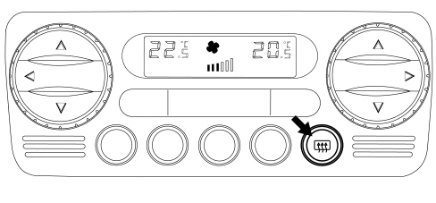
The defrosting of the rearscreen is activated both through the special button and through the Max-Def procedure. The display of the function status takes place through the LED switching on/off.
The function requesting the activation of the heated rear windscreen is only subject to the key-on condition.
COMPONENTS
Air conditioning casing
The air conditioning casing, in other words the plastic structure fastened to the dashboard supporting crossmember, is different for the manual and automatic versions.
Automatic air conditioning casing
The diagram below shows the automatic system components.
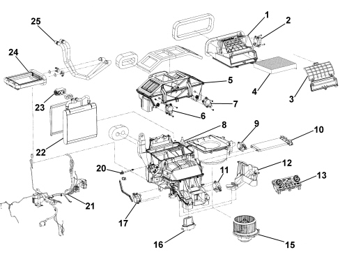
1. Air intake assembly
2. Recirculation actuator
3. Pollen filter cover
4. Pollen filter
5. Ventilation air distribution partition
6. Left distribution actuator
7. Right distribution actuator
8. Climate control system
9. Right mixture actuator
10. Additional heater (PTC)
11. Rear distribution actuator
12. Cover
13. Main climate control system control unit (NCL)
15. Fan
16. Fan speed regulator
17. Left mixture actuator
20. Mixed air temperature sensor
21. Wiring
22. Evaporator
23. Expansion valve
24. Heater
25. Heater pipes
Flaps
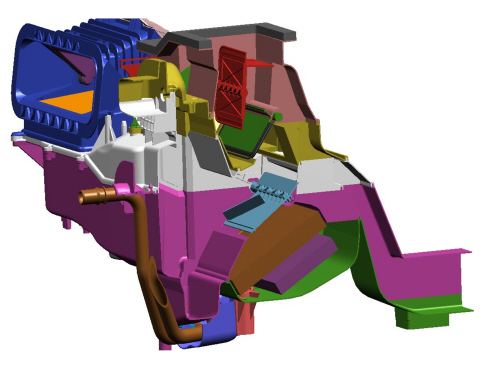
The flaps are the traditional type inside the climate control system, whilst there are new partitions in the upper area of the air distribution which the actuators roll and unroll opening and closing the passage areas.
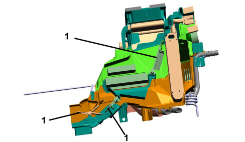
1. Traditional flaps
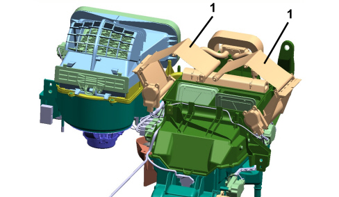
1. Blind partitions
Actuators
There are six actuators on the unit that are controlled by the electronic control unit via a BUS communication line.
Even if they are formally identical, the various actuators are not interchangeable because they are personalized by specific programming.resrm They are managed individually by the Parts Dept.
Mixed air sensor
There is a single evaporator outlet air temperature sensor housed in the air conditioning unit. Depending on the signal coming from this sensor and from the other inpuet parameters (outside air temperature, inside air temperature, air flow rate, solar sensor, etc.) the control unit applies a specific algorithm based on experimental operating maps and controls the various actuators on the basis of the requests made by the users.
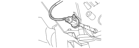
Internal air sensor
It is incorporated in the climate control system control unit and has a fan designed to prevent the build up of air inside it and make the temperature reading as consistent as possible.
Manual air conditioning casing
The diagram below shows the manual system components.
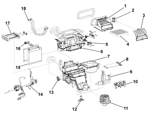
1. Air intake assembly
2. Recirculation actuator
3. Pollen filter cover
4. Pollen filter
5. Distribution actuator
6. Upper distribution assembly
7. Climate control system
8. Additional heater (PTC)
9. Cover
10. Climate control system control unit (NCL)
11. Fan
12. Fan speed adjustment resistors
13. Mixture actuator
14. Wiring
15. Evaporator
16. Expansion valve
17. Heater
18. Heater pipes
Flaps and actuators
The flaps are the traditional type controlled by actuators with electric stepping motors.
Solar sensor
The solar sensor (fitted for the automatic climate control) is located on the top part of the dashboard at the base of the windscreen.
Its task is to transform the light signals (lux or kcal/m²h) into a corresponding linear electrical signal to supply a value proportional to the thermal energy introduced into the passenger compartment through the windscreen through the effect of the sun''s rays.
It is only fitted on the automatic climate control version.
The sensor is a special type of diode (photodiode) which can alter its conduction depending on the quantity of light coming into contact with it.
If the climate control system control unit (NCL) is managing the system in AUTO mode, it uses this signal and alters the air temperature and distribution parameters to maintain the temperature requested by the user.
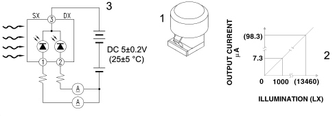
1 - Solar sensor
2 - Output lighting - current typical diagram
3 - Diagram showing operation of solar sensor
Outside air temperature sensor
This is an NTC sensor (present for the automatic climate control system) fitted on the lower part of the left exterior rear view mirror.
It supplies a signal to the electronic control unit proportional to the temperature of the outside air.
Intake air quality sensor (aqs)
The AQS sensor (available on request for the automatic climate control system) is an electronic device that is designed to supply a signal to the climate control unit when the air pollution index exceeds a preset danger level. The control unit manages the automatic recirculation function to prevent the introduction of polluted air into the passenger compartment. The sensitive element of the sensor is capable of detecting the presence of oxidizing particles (e.g. CO) or reducing particles (e.g. NOx) in the flow or air entering the vehicle.
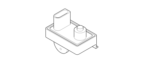
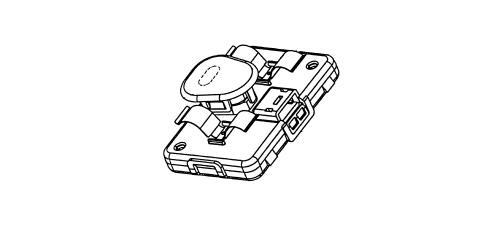
Misting sensor (fog sensor)
This sensor (available on request for the automatic climate control system) is housed in the area of the interior rear view mirror with the sensitive element facing the interior surface of the windscreen/ An electronically managed optical system makes it possible to detect the degree of misting of the windscreen and provides a series of signals for the control unit depending on the pre-set intervention levels.
The signal is represented by a train of impulses with a Duty Cycle that varies between 10% and 90%.
Expansion valve
The tasks of this valve are to:
- Separate the high pressure circuit from the low pressure circuit;
- Expand the refrigerant (change in state from liquid to gas);
- Regulate the evaporation process (flow rate);
- Regulate the evaporation temperature;
- Protect the compressor from refrigerant fluid.
The thermostatic expansion valve is fitted on the evaporator inlet and outlet ducts with the task of regulating the flow and expansion (drop in pressure) of the R134a fluid before entry into the evaporator.
The automatic regulation of the size of the passage for the gas inside the expansion valve is produced by a sensitive bulb which measures the temperature of the refrigerant fluid and depending on this suitably adjusts the size of the opening that the gas passes through by means of a special spring that moves a shutter determining the extent of the expansion.
The increase in temperature at the evaporator outlet, detected by the bulb, ensures that the valve is opened with a consequent increase in the flow rate of the fluid in the evaporator.
Conversely, low temperatures involve a reduction in the size of the gas port determining a decrease in the flow of gas.
The expansion valve is directly accessible from the engine compartment.

Linear pressure switch
The linear pressure switch makes sure the system is working properly. By continuously analyzing the pressure of the climate control system circuit, the sensor provids the engine management control unit, in real time, wih the variations in pressure making the management of the activation levels more flexible.
For each variation in pressure there is a corresponding voltage signal used by the engine management control unit to activate the fan speed and switch off the compressor if the pressure increases or decreases beyond the permitted limits (safety function).
The operating range of the linear sensor goes from 3.018 bar up to 29.508 bar according to the following pressure (bar) / output voltage percentage (%Vcc) curve.
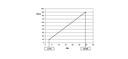
The go ahead for the activation of the compressor and the adjustment of the fan speed, depending on the variation in pressure, takes place in this pressure range; the compressor is deactivated above and below these values for safety reasons to prevent damage to the system.
The pin out for the sensor is illustrated in the diagram below.
The supply voltage can vary by ±10% and the temperature of the sensor is between -5°C and 80°C.
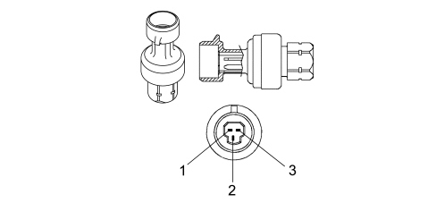
1 - Earth
2 - Supply voltage
3 - Output signal
Compressor
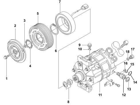
1. Bolt
2. Guide plate
3. Size
4. Seal
5. Pulley assembly
6. Seal
7. Electromagnet coupling
8. Shaft seal assembly
9. Oil drain plug
10.O-ring
11. Compressor
12. Control valve
13.Sealing ring
14. O-ring
15. O-ring
16. O-ring
17. Safety valve
18. O-ring
The compressor is the oscillating disc type:
With this type of compressor the cylinders and pistons are arranged axially along the crankshaft. The pistons work inside the cylinders and are controlled by an oscillating disc to produce the intake, compression and exhaust strokes. In variable capacity compressors, with oscillating discs, the angle of the oscillating disc is altered to change the stroke of the piston and the capacity.
Oscillating disc
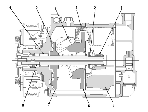
The crankshaft (8), which is operated by the engine by means of an electromagnet coupling, is equipped with a thrust flange (7) and is connected by a joint (3) to the oscillating plate (6).
The crankshaft is supported by two radial bearings (1) and two thrust bearings (2). The oscillating plate is controlled with an alternating motion by the rotation of the crankshaft and operated by the alternating motion of the pistons (4).
Movement of the pistons
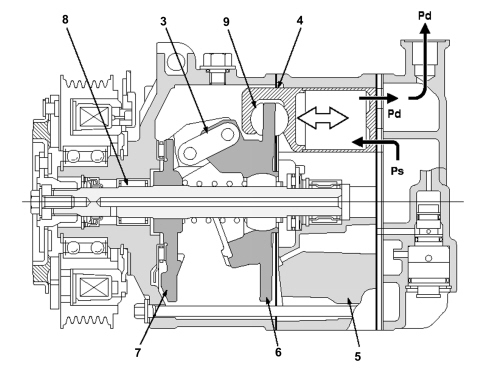
Pd: Exhaust pressure
Ps: Intake pressure
The pistons in the cylinders are connected to the oscillating disc by two plates (9). The rotation of the thrust flange (7) is transformed into the alternating motion of the oscillating disc (6) and the pistons (4).
The cylinder block (5) has seven cylinders evenly arranged around the crankshaft. The pistons work inside the cylinders and produce the intake and compression strokes.
Control of the stroke
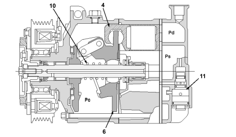
Pd: Exhaust pressure
Ps: Intake pressure
Pc: Internal chamber pressure
The control valve (11) on the cylinder head governs the flow of gas in the internal chamber depending on the intake pressure (Ps) and the exhaust pressure (Pd) which represent the thermal load.
A reaction spring (10) is housed at the front of the oscillating disc.
The force of the spring, the thrust of the gas on the piston crown and the thrust of the internal chamber (Pc) on the rear surface of the piston produce a torque that controls the angle of the oscillating disc (6) and vary the stroke of the piston (4).
Operation
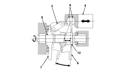
The thrust flange (7) on the crankshaft (8) and the variable angle oscillating disc (6) are connected by a joint (3).
The joint acts as a fulcrum and the angle of the oscillating disc is altered by the ball joint (12) on the oscillating disc that moves along the crankshaft.
The rotation of the oscillating disc (6) is converted into an alternating motion by the movement of the ball joint (12). The piston is fitted on the oscillating disc by means of two plates (9). The stroke of the piston is altered according to the angle of the oscillating disc to produce the variation in the cylinder capacity.
Condenser with integrated drier filter
The condenser is a heat exchanger located in front of the engine coolant radiator.
Its task is to condense the refrigerant fluid, in other words transform it from a gaseous state to a liquid state.
The refrigerant fluid in a gaseous state passes throug the condenser pipes and liquifies, on average, at a temperature of 60°C.
The air comes into contact with the condenser. When the vehicle is stationary or driving in traffic, the flow of air is produced by the engine radiator fan.
An insufficient thermal exchange in the condenser causes an increase in the pressure in the system and the incomplete condensation of the fluid thereby reducing the efficiency of the system.
There is a housing on the left side of the condenser for the drier filter. This allows the layout of the system to be improved.
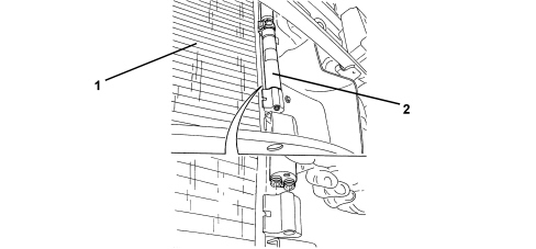
1. Condenser
2. Built-in drier filter
Fan
On the manual system, the fan is activated by the passenger compartment air speed selector which sends the signal to a resistive divider which produces the different speeds. The resistive divider is fitted in the duct between the dynamic air intake and the unit to cool it.
In the automatic system the fan is operated by dedicated buttons in the control panel which send the signal to the Climate Control Node which produces different voltage values for the different speeds.
Pollen filter
The pollen filter is designed to filter the outside air entering the passenger compartment.
It is located inside the air conditioning casing and can be replaced by removing the oddments compartment in the area of the passenger.
The filter is fitted on both the manual version and the automatic version of the climate control system.
Parts & tools for this job Staging For 2005 Alfa Romeo Brera
- TOOLA/C manifold gauge setSearch: AC manifold gauge set
- TOOLUV leak detection kitSearch: AC UV leak detection kit
- PARTCabin filterSearch: Alfa Romeo Brera 2005 cabin filter
Links open Amazon search results in a new tab. As an Amazon Associate I earn from qualifying purchases.