
E4021 Speedometer (Euro3)
- Make
- Alfa Romeo
- Model
- 156 Factory Service Manual
- Year
- 1997–2002
- Section
- Instruments › E4021 Speedometer (Euro3)
E4021 Speedometer (Euro3)
Description
The module includes
- electronic speedometer
- milometer and trip meter / outside temperature gauge;
- and a series of warning lights.
The speedometer signal comes from the ABS control unit; there are three 'repeater' outputs of the signal for other systems; only two are used for the electronic fuel injection and climate control system. The gauge display is produced by an electronic circuit inside the module.
The milometer consists of an LCD which simultaneously displays the total and trip mileage.
A special button zeros the trip meter and allows the outside temperature to be displayed. For greater detail, see Characteristic of working principle 5560 Instruments .
The outside temperature reading comes from the climate control unit Characteristic of working principle 5040 Air conditioner box and components .
The button is on the left of the instruments, together with the instrument light adjustment button and the headlamp alignment control.
The following warning lights are contained in this module:
- seat belts
- brake pad wear
- maximum catalytic converter temperature (preparation)
- heater plugs
- passenger Air Bag disabling
- water in diesel filter
The seat belts warning light comes on when the ignition is switched ON for about 15 seconds, irrespective of whether or not the belts are fastened, to remind the driver and passengers.
The brake pad warning light comes on for about 4 seconds, when the ignition is switched ON, to check that they are working properly, then it goes out.
The electronic circuits inside the module also manage the test function for the warning lights of all the modules: Wiring diagram E4040 WARNING LIGHTS CHECK .
The operation of the warning lights which are not included in other functions is illustrated; the others are described and illustrated in the diagrams dealing with the components to which they refer.
The speedometer operates when the ignition is switched ON.
In the 'night' conditions (side lights on), the brightness can be adjusted to three levels by an external button. Wiring diagram E2530 INSTRUMENT LIGHTING
Description of operation
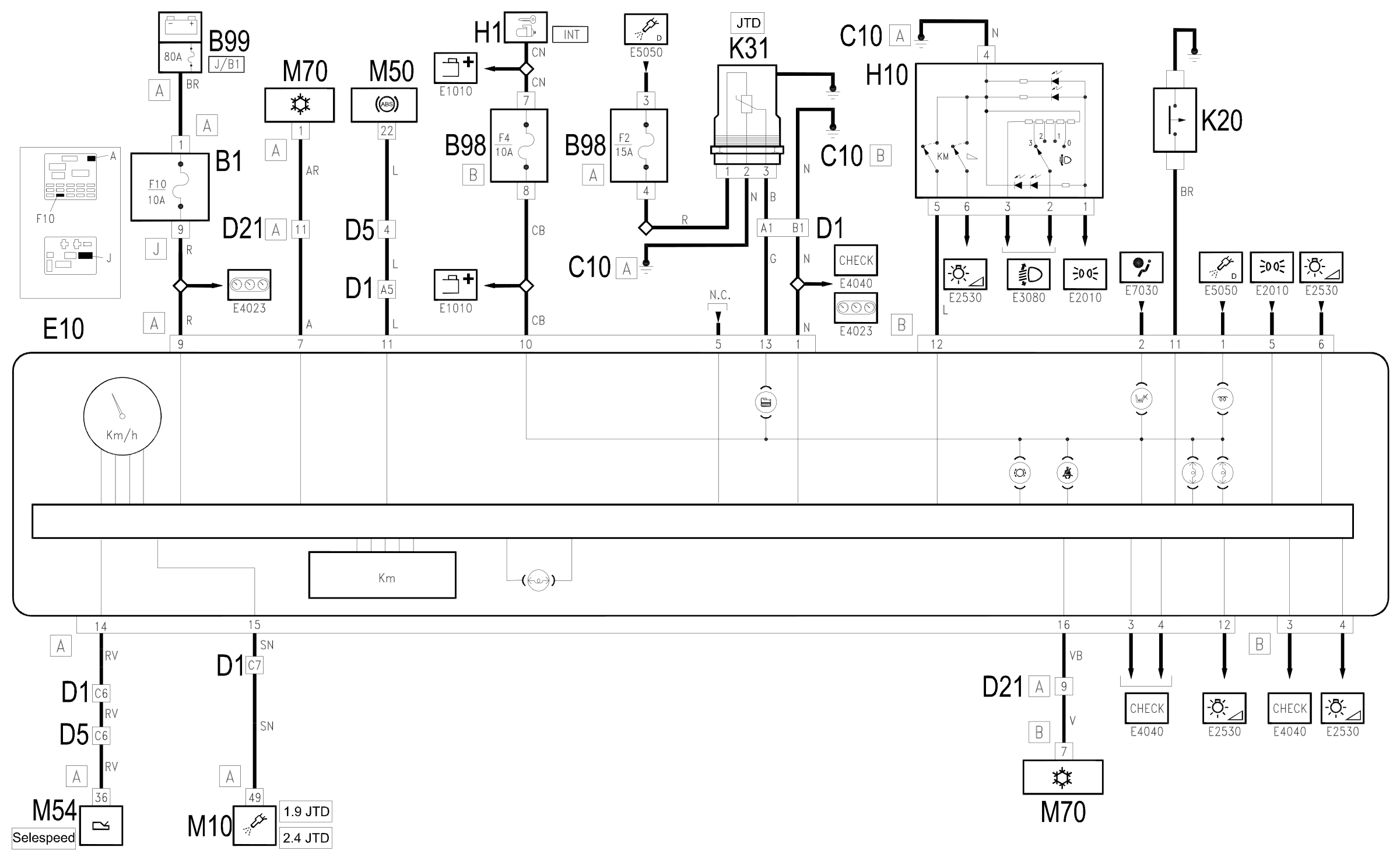
The supply to the speedometer module E10 reaches pin 9 of connector A directly from the battery (maxifuse J/B1of B99), via fuse F10 of the junction unit B1; the supply controlled by the ignition (INT) reaches pin 10 of connector A from the line protected by fuse F4 of the additional fuse box B98B.
Pin 1 of connector A is earthed.
The ABS control unit M50 sends the speedometer signal to pin 11 of connector A of E10.
The speedometer signal is sent again from pin 15 of connector A to the engine control unit M10 (JTD engines only) and from pin 16 of connector A towards the climate control unit M70.
u
The same signal is sent from pin 14 of connector A to the automatic transmission control unit M54.
Pin 7 of connector A of E10 receives the signal for the outside temperature from the climate control unit M70.
The zeroing signal for the trip meter reaches pin 12 of connector B from H10.
The switch H10 has ideograms lit up when the side lights are switched on through the line coming from the switch for the steering column switch unit H5. Wiring diagram E2530 INSTRUMENT LIGHTING .
The earth signals which provide information on the state of wear of the brake pads, coming from sensor K20, reach pin 11 of connector B.
For all the other warning lights, refer to the diagrams relating to the components to which they refer.
The water in diesel filter sensor K31 is supplied by the line protected by fuse F24 of the additional fuse box B98 A, and sends an earth signal to pin 13 of connector A of the speedometer module E10 when a certain level of humidity is detected in the diesel filter.
Wiring diagram
Components
| Code | Component | See |
|---|---|---|
| B01 | Junction unit | description 5505A |
| B05 | MAXI FUSE-1 box | |
| B11 | Controls lighting fuse | |
| B98 | Supplementary fuse box | description 5505A |
| B99 | Maxifuse box on battery | |
| C10 | Front left earth | description 5505A |
| C31 | Rear right earth | description 5505A |
| D01 | Front / dashboard connection | |
| D04 | Front/engine connection | |
| D05 | Front / ABS couping | |
| D21 | Dashboard/air conditioning-heater connection | |
| E10 | Speedometer | description 5560B |
| H01 | Ignition switch | description 5520A |
| H10 | Switch headlamp adjuster instrument lightzero milometer | description 5540C |
| I45 | Seat belts warning light switch | |
| K20 | Left brake pad wear sensor (switch) | |
| K21 | Right brake pad wear sensor (switch) | |
| K31 | Water in diesel filter sensor | |
| M10 | Engine management ECU | |
| M10 | Engine management control unit | description 1056B |
| M10 | Engine management control unit | description 1060G |
| M50 | ABS control unit | description 3340A |
| M54 | Selespeed transmission control unit | description 2127E |
| M70 | Climate control system control unit | description 5040D |
Component location
Parts & tools for this job Staging For 1997 Alfa Romeo 156
- TOOLDigital multimeterSearch: automotive digital multimeter
- PARTAssorted fuse kitSearch: car fuse assortment kit
- TOOLWire crimper and connector kitSearch: wire crimper connector kit
Links open Amazon search results in a new tab. As an Amazon Associate I earn from qualifying purchases.