
E2530 Instrument lighting
- Make
- Alfa Romeo
- Model
- 156 Factory Service Manual
- Year
- 1997–2002
- Section
- Interior lighting › E2530 Instrument lighting
E2530 Instrument lighting
Description
All the instruments (dials and gauges) are lit up with the ignition switched ON.
In the "night" position (side lights on), the brightness can be adjusted to three levels by an external button.
On the sport version with white dials, these are not illuminated when the ignition is switched on, only when the side lights are switched on.
This lighting logic is managed by a speedometer module which controls lighting of the rev counter module and the central instrument.
The check control instrument is lit up directly by the electronic device inside.
The adjustment button is on the left of the actual instruments, together with the button for zeroing the milometer and the headlamp alignment adjuster.
The lighting circuit for all the instruments is protected by a special fuse, located at the side of the junction unit.
Description of operation
The supply for the speedometer E10 (pin 10 of connector A) is controlled by the ignition (INT) by the line for fuse B11 up to 2/99 or fuse F4 of the additional fuse box B98B from 2/99.
Similarly, the rev counter E15 (at pin 15 of connector A) and the centre instrument E20 (pin 1.).
An earth signal from instrument light dimmer control H10 reaches pin 6 of connector B of E10. This also receives a side light activated signal, at pin 5 of connector B ( Wiring diagram E2010 SIDE LIGHTS / NUMBER PLATE ).
According to the logic processed by the internal electronic device, the speedometer E10 sends the lighting signal to the other instruments: to the centre instrument E20 (pin 7) from pin 12 of connector A; and to the rev counter E15 (3 of connector B) from pin 4 of connector B.
Switch H10 symbols are lit up when the side lights are switched on through the line coming from the switch for the steering column switch unit H5.
Wiring diagram
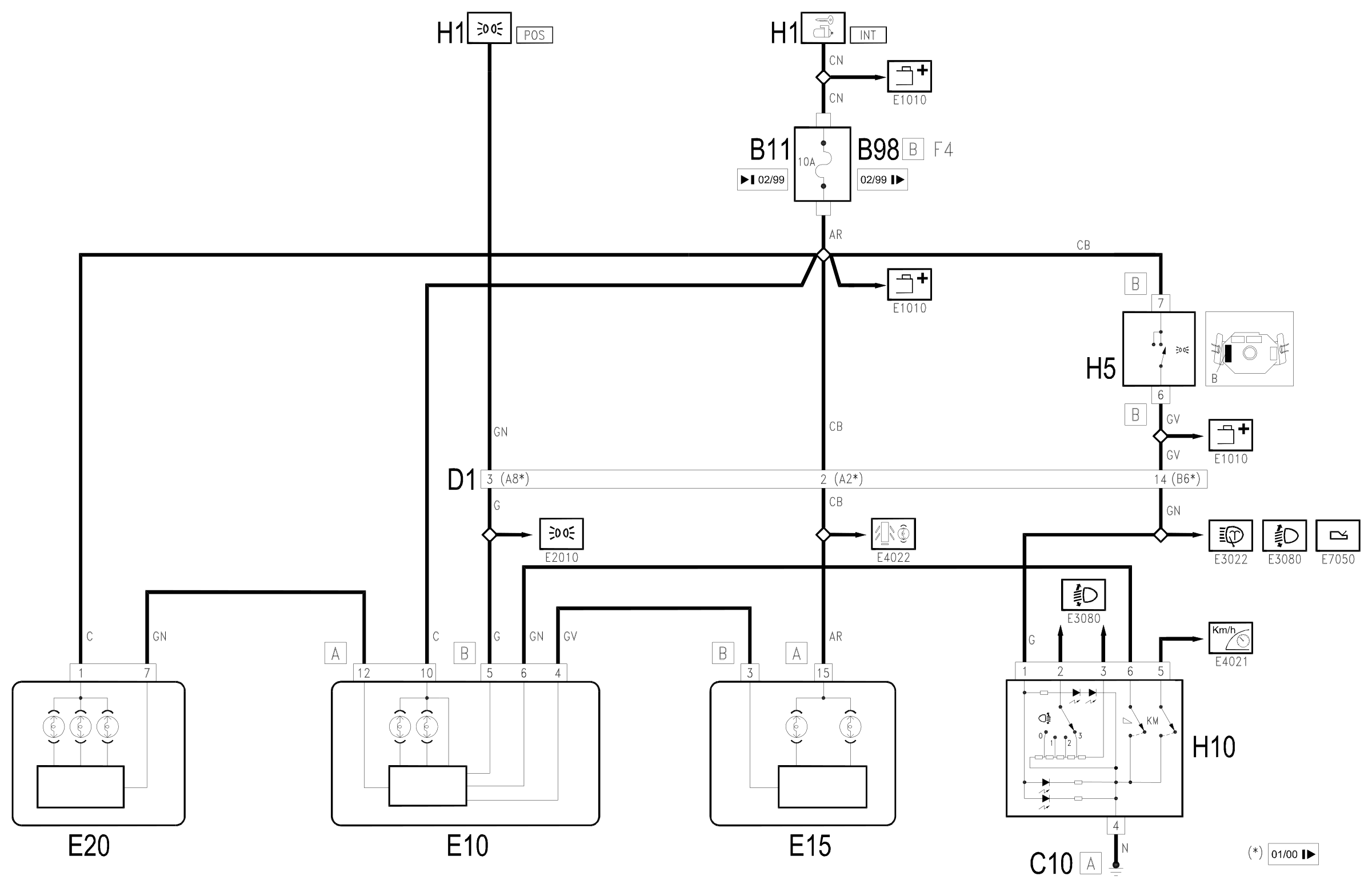
Components
| Code | Component | See |
|---|---|---|
| B11 | Controls lighting fuse | |
| B98 | Supplementary fuse box | description 5505A |
| C10 | Front left earth | description 5505A |
| D01 | Front / dashboard connection | |
| E10 | Speedometer | description 5560B |
| E15 | Rev counter | description 5560B |
| E20 | Auxiliary instrument | description 5560C |
| H01 | Ignition switch | description 5520A |
| H05 | Steering column switch unit | description 5550A |
| H10 | Switch headlamp adjuster instrument lightzero milometer | description 5540C |
Component location
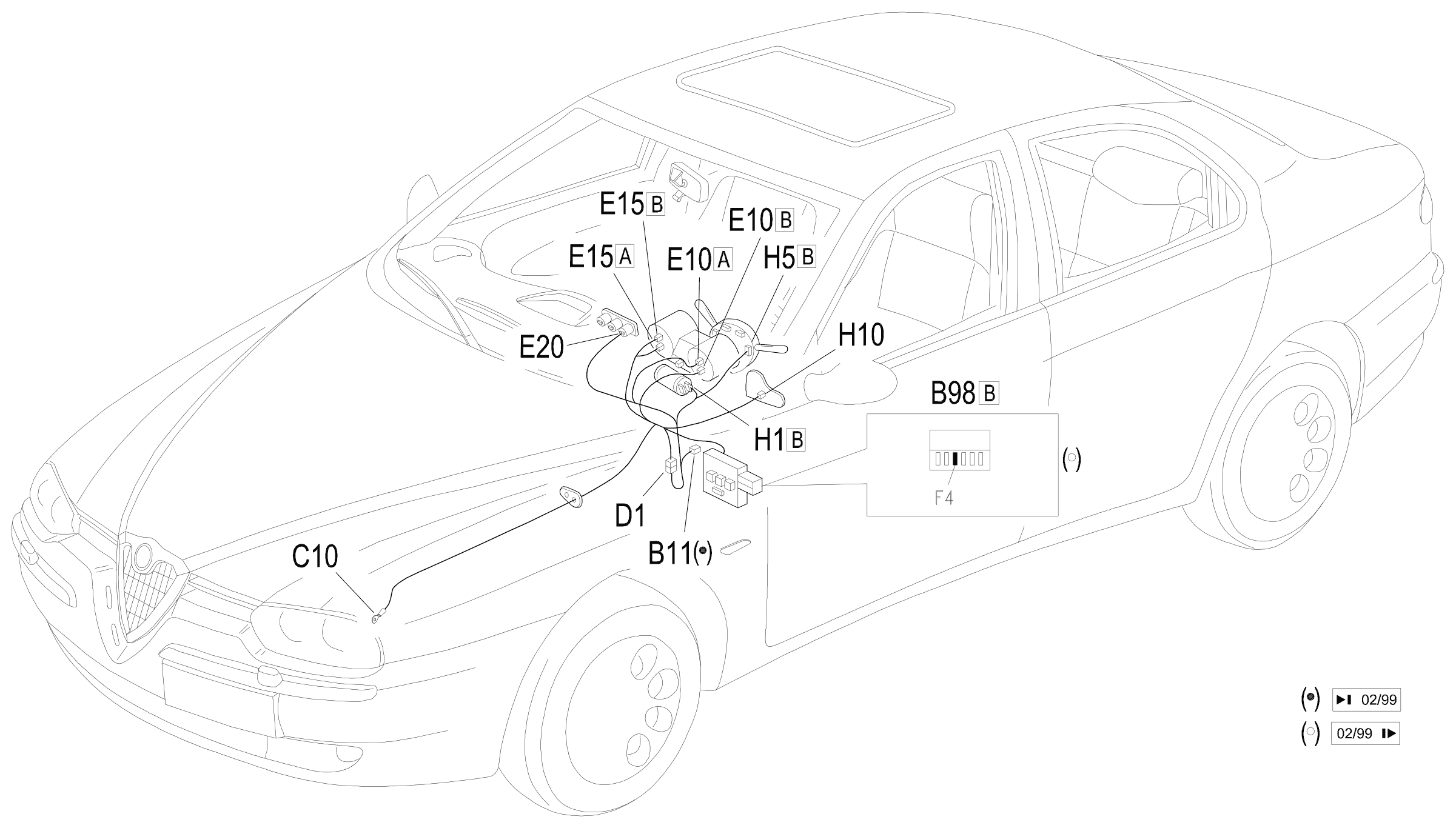
Parts & tools for this job Staging For 1997 Alfa Romeo 156
- PARTReplacement bulbsSearch: Alfa Romeo 156 1997 bulbs
- TOOLDigital multimeterSearch: automotive digital multimeter
Links open Amazon search results in a new tab. As an Amazon Associate I earn from qualifying purchases.