
E8010 Diagnostics multiple connector (Euro3)
- Make
- Alfa Romeo
- Model
- 156 Factory Service Manual
- Year
- 1997–2002
- Section
- Diagnostic systems › E8010 Diagnostics multiple connector (Euro3)
E8010 Diagnostics multiple connector (Euro3)
Description
The car is equipped with numerous self-diagnostic electronic control units.
When a tester (Examiner or other instrument) is connected to the control units, self-diagnostic data can be read (parameters, errors) or active testing can be carried out.
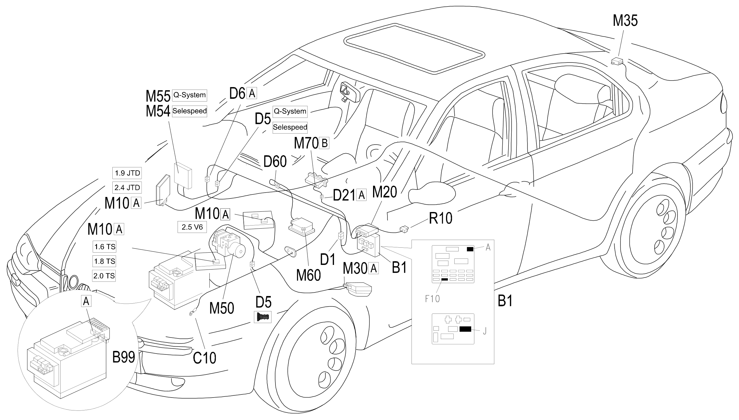
This car is not fitted with a specific tester connection for each control unit. Instead, a single standard 16-way tester connection is located on the left hand side of the facia, above the junction unit.
The diagnostic equipment (Examiner or other instruments) is connected to it using a special adaptor. This adaptor makes it possible to select the system to which you wish to connect.
Description of operation
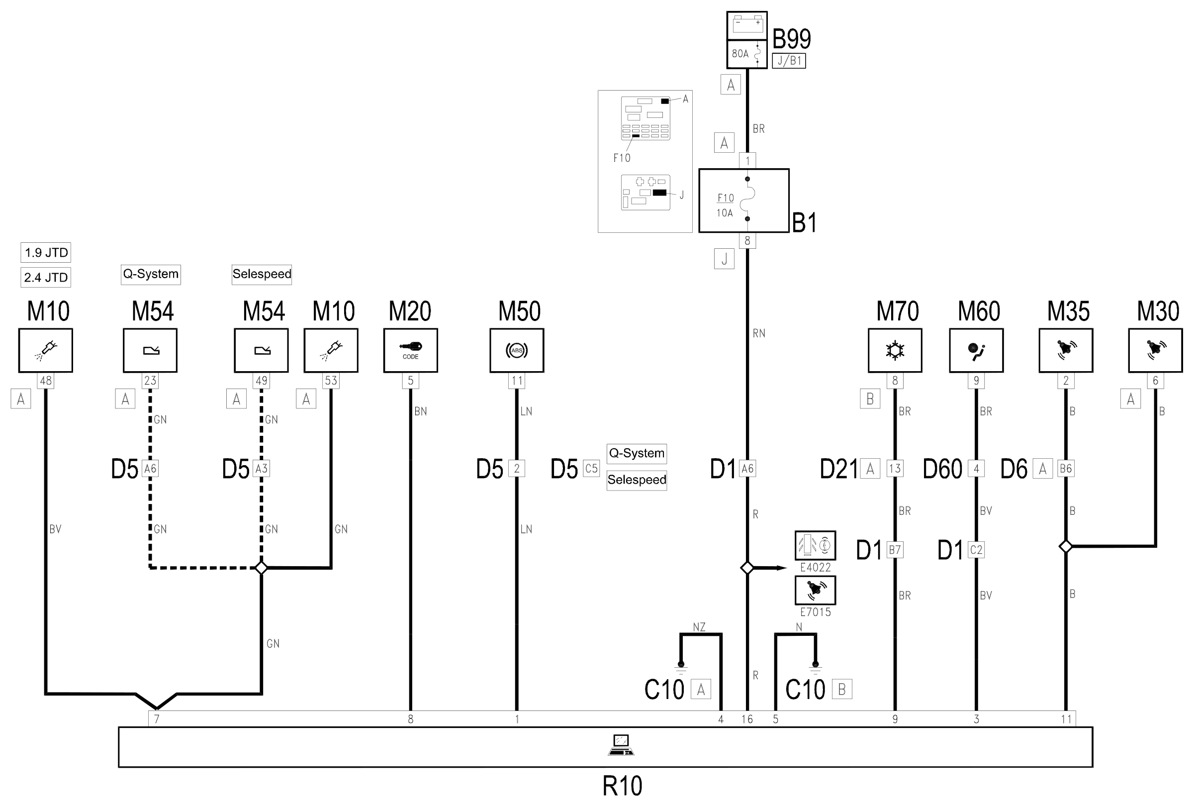
The diagnostic socket R10 is supplied directly by the battery at pin 16 by the line protected by fuse F10 of the junction unit B1.
Pins 4 and 5 are earthed.
The pins are connected to the ABS control unit M50 (pin 11) Wiring diagram E7020 ABS .
Pin 3 is connected to airbag control unit M60 (pin 9) Wiring diagram E7030 AIRBAG .
Pin 9 is connected to the climate control unit M70 (pin 8 of connector B) Wiring diagram E6020 AIR CONDITIONER .
Pin 11 is connected to alarm control unit M30 (pin 6 of connector A) and remote control receiver M35 (pin 2) Wiring diagram E7015 ALARMS .
Pin 8 is connected to Code control unit M20 (pin 5) Wiring diagram E7010 CODE .
abdf
Pin 7 is connected to the engine management control unit M10 (pin 53 of connector A) Wiring diagram E5030 PETROL ENGINES ELECTRONIC CONTROL .
u
pin 7 is connected to the SELESPEED control unit M54, which shares its test line with engine management unit M10 Wiring diagram E7050 AUTOMATIC TRANSMISSION .
v
pin 7 is connected to AISIN electronic automatic transmission management unit M55, which shares its test line with engine management unit M10 Wiring diagram E7050 AUTOMATIC TRANSMISSION .
ce
Pin 7 is connected to engine management control unit M10 (pin 48 of connector A) Wiring diagram E5050 DIESEL ENGINES ELECTRONIC MANAGEMENT .
Wiring diagram
Components
| Code | Component | See |
|---|---|---|
| B01 | Junction unit | description 5505A |
| B05 | MAXI FUSE-1 box | |
| B99 | Maxifuse box on battery | |
| C10 | Front left earth | description 5505A |
| D01 | Front / dashboard connection | |
| D04 | Front/engine connection | |
| D05 | Front / ABS couping | |
| D06 | Front / rear connection | |
| D21 | Dashboard/air conditioning-heater connection | |
| D60 | Air Bag connection | |
| M10 | Engine management ECU | |
| M10 | Engine management control unit | description 1056B |
| M10 | Engine management control unit | description 1060G |
| M20 | CODE control unit | description 5580E |
| M30 | Alarm control unit | description 5580E |
| M35 | Alarm remote control receiver | description 5580E |
| M50 | ABS control unit | description 3340A |
| M54 | Selespeed transmission control unit | description 2127E |
| M55 | Automatic transmission control unit | description 2135B |
| M60 | Air bag control unit | description 5580C |
| M70 | Climate control system control unit | description 5040D |
| R10 | Multiple tester connection |
Component location
Parts & tools for this job Staging For 1997 Alfa Romeo 156
- TOOLOBD2 scannerSearch: OBD2 scanner
- TOOLDigital multimeterSearch: automotive digital multimeter
- TOOLBack-probe test leadsSearch: back probe test leads
Links open Amazon search results in a new tab. As an Amazon Associate I earn from qualifying purchases.