
E7030 Airbag
- Make
- Alfa Romeo
- Model
- 156 Factory Service Manual
- Year
- 1997–2002
- Section
- Car electronic systems › E7030 Airbag
E7030 Airbag
Description
The car may be fitted with an electronically-controlled safety system that sets off the front seat belt pretensioners and the driver's air bag, passenger air bag and sidebags in the case of frontal and/or side impact of a certain severity.
An electronic control unit manages the entire system by controlling all the components and activating the restraint systems (pretensioners and airbags) as necessary.
The control unit has two different intervention levels:
- at the first level only the pretensioners are activated
- the second level operates both airbags and pretensioners.
The control unit is located under the centre console and is rigidly fixed to the bodyshell: in this way the deceleration sensors located inside it are close to the centre of gravity and detect deceleration for the entire vehicle accurately.
The driver's Air Bag module is located in the centre of the steering wheel; it is fitted on a tilting plate which enables the horn to be operated. The plate houses a metal container which holds the folded airbag and a gas generator that inflates the bag.
A clock spring device allows the airbag module connection leads to turn with the steering wheel without the risk of breakage.
The passenger airbag is located on the facia, above the glove compartment, and is fastened directly to the car crossmember via a special bracket.
Ì
The passenger airbag may be deactivated manually via a special switch or automatically by a sensor in the seat.
The switch, which is ignition-activated, is located at the end of the facia on the passenger side and is accessible only with the door open. When the key is turned to OFF, the control unit also controls the activation of a passenger air bag disablement warning light.
Ì
The seat houses an automatic passenger presence detection sensor. This takes the form of electrical resistors that detect the presence or absence of a passenger.
The pretensioner is a device built into the front seat belt reel.
It cuts in to take up the inevitable lengthening of the seat belt due to the action of the body in order to hold the body against the seat squab.
The control unit comes with a self-diagnostic function.
- it detects and memorizes any faults
- it recognizes the various components and the type of fault
- to indicate the presence of faults via a warning light
System activations following a particularly serious impact are memorized by the control unit.
For more details see DESCRIPTION AND OPERATION: 5580C Air bag system .
The system control unit supply lines are protected by a fuse located next to the junction unit.
there are two possible configurations for the system.
- the "standard" configuration., fitted as standard, where there is a driver's Air Bag and two pretensioners.
- the complete configuration, which is optional and where there is also a passenger Air Bag and disabling devices.
When operations are carried out to the Air Bag system the recommended safety instructions must be followed precisely. For more details See assembly drawing 5580C Air bag system
ú
For a period the passenger presence sensor has not been fitted; instead, while awaiting the modified control unit and wiring, the sensor has been temporarily replaced by a specific simulation resistor so as not to cause the detection of an error by the control unit's self-test system.
Description of operation
The Air Bag system control unit M60 receives a supply controlled by the ignition (15/54) at pin 15 from the line protected by shunt fuse B30 up to 3/98 or B32 from 3/98.
up to 2/99 or from fuse F5 from supplementary fuse box B98A from 2/99.
Pin 14 is connected to the specific earth C50, like pin 30, on "complete" versions, i.e. with a passenger Air Bag. (on versions with a driver's Air Bag only, pin 30 is not connected).
When an impact of a set severity (determined by the control software) is detected, the control unit sends control signals to set off the modules:
- to driver's Air Bag Q9, via the steering wheel clockspring Q10 (from pins 1 and 2):
- to passenger airbag Q11 (from pins 3 and 4);
- to driver's side pretensioner Q20 (from pins 10 and 11) and passenger side pretensioner Q21 (from pins 6 and 7).
ú
Pins 23 and 27 are connected to the sensor in the seat for disabling the passenger Air Bag K65.
Pins 5 and 24 are connected to the passenger Air Bag disabling switch H75.
When the system self-diagnostic function detects a fault or an impact is detected, control unit M60 sends a signal - from pin 13 - to the airbag failure warning light located in instrument panel E30. This signal causes the warning light to come on because instrument E30 is supplied via the ignition (INT) from a line protected by the control light fuse B11 up to 2/99 or by fuse F4 of supplementary fuse box B98B from 2/99.
Self-diagnostic data may be read by connecting the unit to connector R10: this receives signals from pin 9 of control unit M60 through the appropriate tester line.
Pin 20 of M60 sends the signal for the "passenger Air Bag disabled" warning light, located in the speedometer E10. This signal causes the warning light to come on because instrument E30 is supplied via the ignition (INT) from a line protected by the control light fuse B11 up to 2/99 or by fuse F4 of supplementary fuse box B98B from 2/99.
Wiring diagram
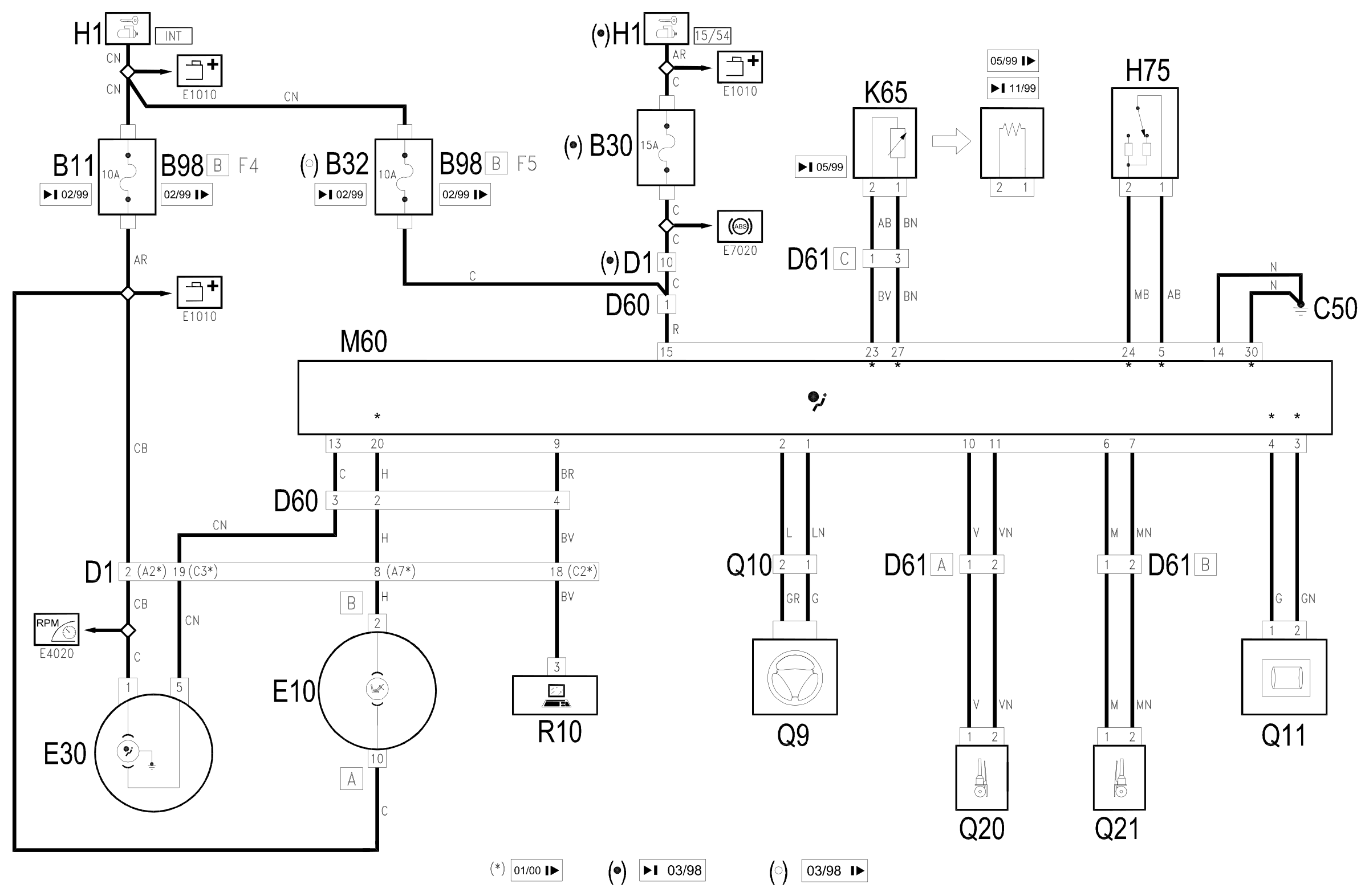
Components
| Code | Component | See |
|---|---|---|
| B11 | Controls lighting fuse | |
| B30 | ABS fuse and Air Bag | |
| B98 | Supplementary fuse box | description 5505A |
| C50 | Air Bag earth | description 5505A |
| D01 | Front / dashboard connection | |
| D60 | Air Bag connection | |
| D61 | Pretensioner connection | |
| E10 | Speedometer | description 5560B |
| E30 | Check control | description 5560C |
| H01 | Ignition switch | description 5520A |
| H75 | Passenger's Air Bag disablement switch | description 5580C |
| K65 | Sensor in seat for disabling passenger's Air Bag | description 5580C |
| K66 | Sensor for driver's Side Bag | description 5580C |
| K67 | Sensor for passenger Side Bag | description 5580C |
| M60 | Air bag control unit | description 5580C |
| Q09 | Driver's Air Bag | description 5580C |
| Q10 | Clock spring on steering wheel | description 5580C |
| Q11 | Air Bag in dashboard (passenger side) | description 5580C |
| Q20 | Driver's seat belt pre-tensioner | description 7065A |
| Q21 | Front passenger seat belt pre-tensioner | description 7065A |
| Q30 | Driver's Side Bag | description 5580C |
| Q31 | Passenger Side Bag | description 5580C |
| Q40 | Driver's Head Bag | description 7095B |
| Q41 | Passenger Head Bag | description 7095B |
| R10 | Multiple tester connection |
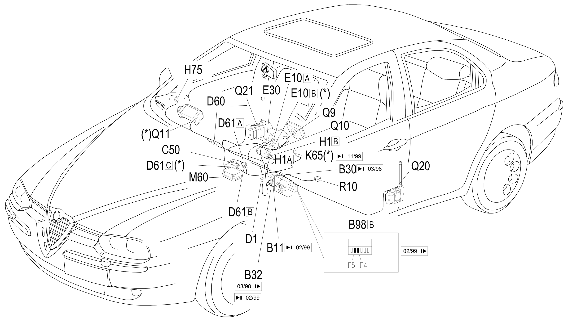
Component location
Parts & tools for this job Staging For 1997 Alfa Romeo 156
- TOOLOBD2 scanner with SRSSearch: OBD2 scanner ABS SRS
- TOOLTrim removal tool kitSearch: trim removal tool kit
Links open Amazon search results in a new tab. As an Amazon Associate I earn from qualifying purchases.