
E2031 Rear fog lamp
- Make
- Alfa Romeo
- Model
- 147 Factory Service Manual
- Year
- 2000–2002
- Section
- Exterior lighting › E2031 Rear fog lamp
E2031 Rear fog lamp
Description
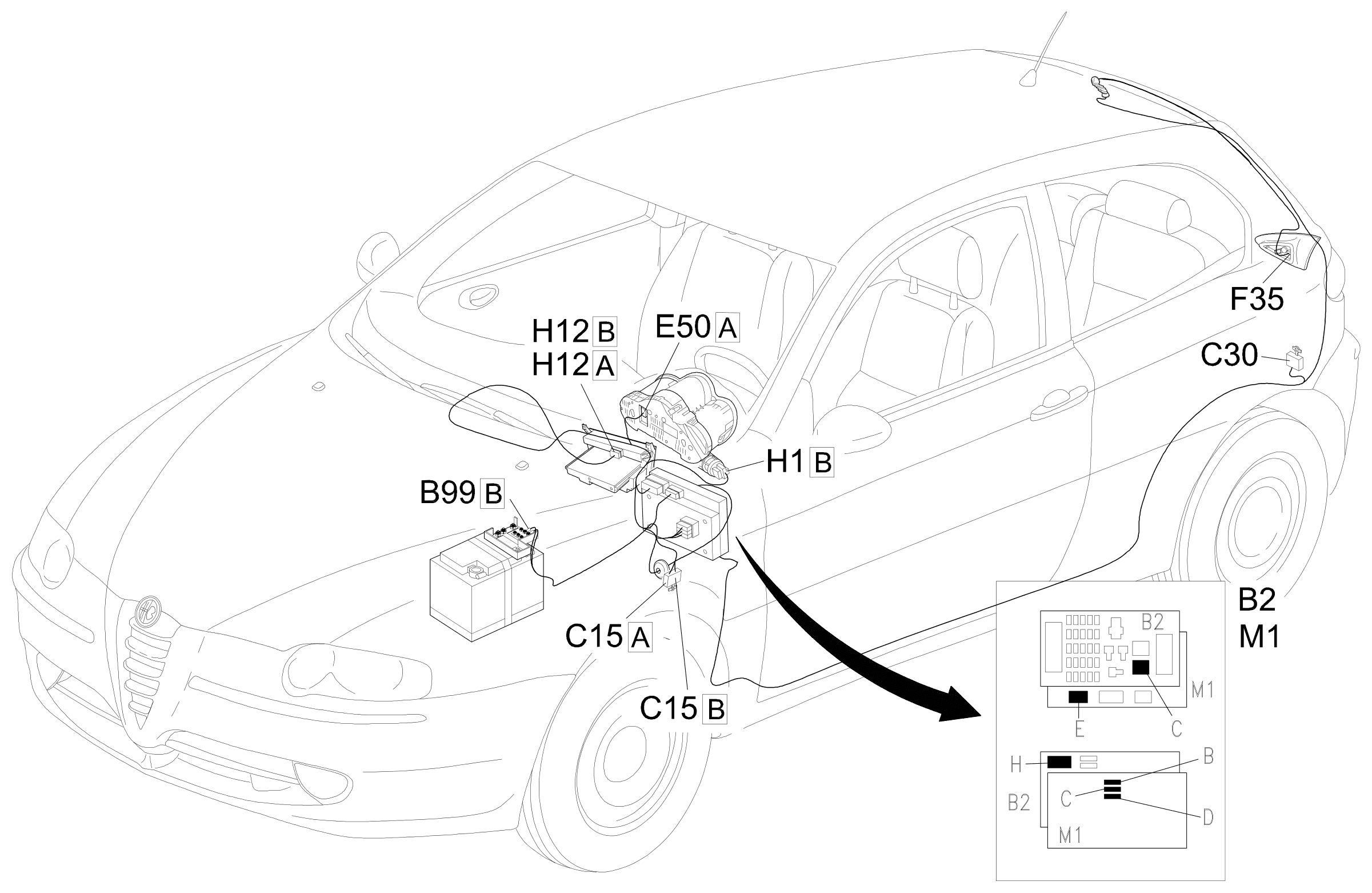
The vehicle is equipped with a bright rear fog lamp, located in the centre of the left rear light cluster (on the boot).
The rear fog lamp is activated via a special button in the centre panel; there is also an LED at the rear of the button which comes on when the light is on.
The switching on of the rear fog lamp is managed by the Body Computer: it is activated in the following conditions:
- go ahead signal with ignition ON (INT);
- signal from the switch in the panel;
- side lights on signal.
- headlamps signal (dipped or main beam) or fog lights on.
If one of the go ahead signals is missing, the button must be pressed again in order to switch the rear fog lamp on.
The correct operation of the light is controlled by the rear fog lamp 'check' function: the following are checked:
- open circuit (bulb missing or wiring broken) which can be diagnosed if there is no command
- short circuit to earth (bulb short circuit or wiring short circuit to earth)
- short circuit to Vbatt (wiring short circuit to Vbatt)
- 21 W bulb replaced with a 5 W bulb
If one of the situations described above is detected, the Body Computer notifies the CAN of the failure state: the special 'lights failure' warning light in the instrument panel comes on and, at the same time, the information is shown on the display.
Description of operation
The rear fog lamps activation signal reaches pin 35 of connector B of M1 from the control button in the panel.
The side lights activation signal is sent to pin 28 of connector B of the Body Computer M1 from the steering column switch unit H5 Wiring diagram E2010 SIDE LIGHTS / NUMBER PLATE .
The dipped headlamps activation signal is sent to pin 4 of connector D of the Body Computer M1 from the steering colun switch unit H5 El2011].
The fog lights activation signal reaches pin 1 of connector D of the Body Computer M1 (see EL2030].
The 'ignition ON' signal (INT) for the switch H1 reaches the underdashboard control unit B2 at pin 11 of connector H and from there moves on to the Body Computer M1 (pin 9 of connector F).
The Body Computer M1 controls the supply of the rear fog lamp F35 from pin 31 of connector E.
The signal is sent, from pin 21 of connector C of M1, to light up the LED in the control button H12.
The Body Computer M1 is connected, via the CAN line, to the instrument panel E50 to manage the 'lights failure' warning light if there is a failure in the circuit.
Wiring diagram
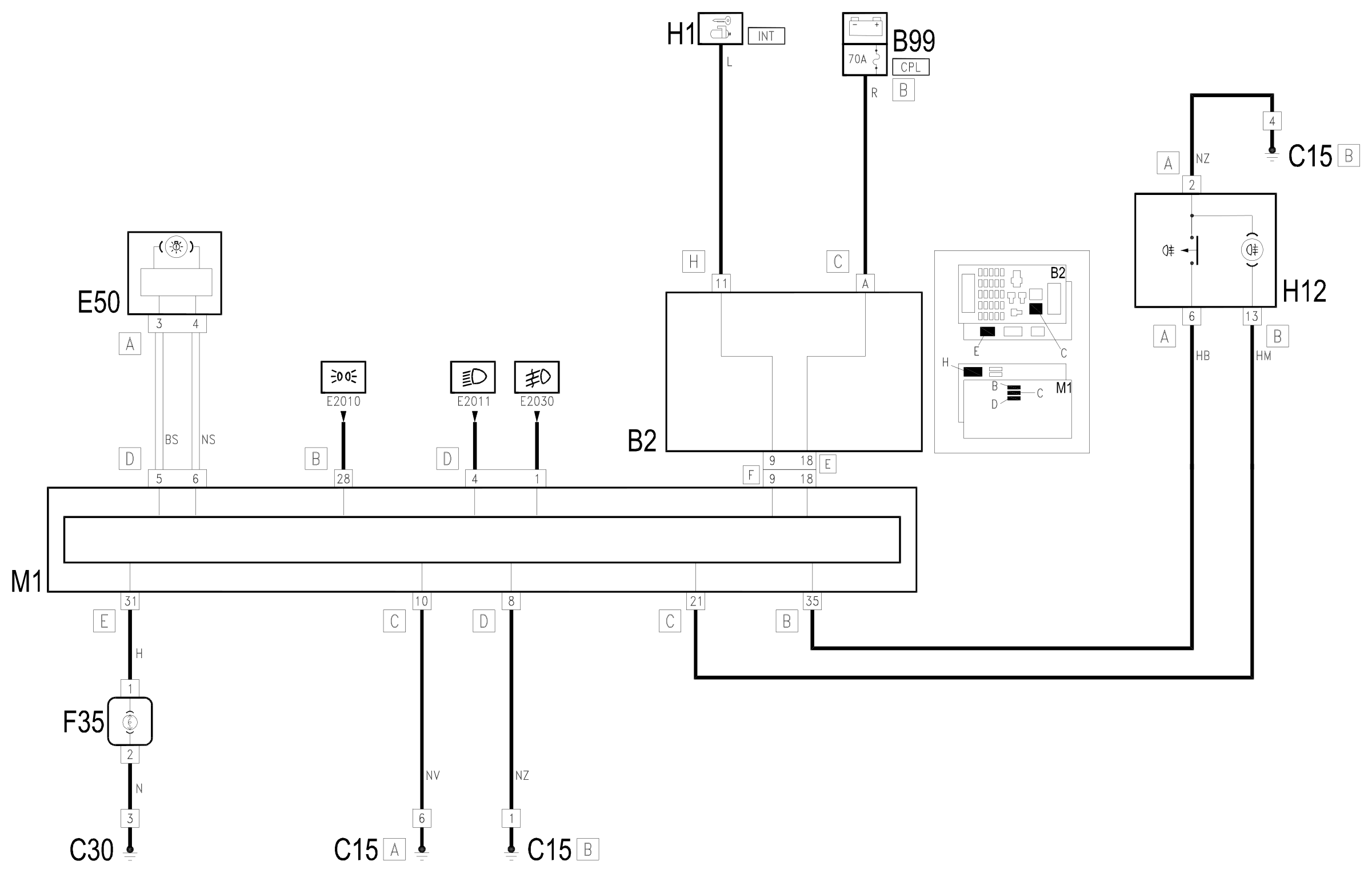
Components
| Code | Component | See |
|---|---|---|
| B02 | Junction unit under dashboard | description 5505A |
| B99 | Maxifuse box on battery | description 5530B |
| C15 | Facia earth, driver's side | |
| C30 | Left rear earth | |
| E50 | Instrument panel | description 5560B |
| F35 | Left rear light cluster (moving part on boot lid) | description 5540E |
| H01 | Ignition switch | description 5520A |
| H12 | Hazard warning lights, fog lights, rear fog lamps control | description 5505A |
| M01 | Body computer | description 5505A |
Component location
Parts & tools for this job Staging For 2000 Alfa Romeo 147
- PARTReplacement bulbsSearch: Alfa Romeo 147 2000 bulbs
- TOOLDigital multimeterSearch: automotive digital multimeter
Links open Amazon search results in a new tab. As an Amazon Associate I earn from qualifying purchases.