
E7021 Asr / tcs
- Make
- Alfa Romeo
- Model
- 147 Factory Service Manual
- Year
- 2000–2002
- Section
- Car electronic systems › E7021 Asr / tcs
E7021 Asr / tcs
Description
The antilock braking and anti-slip regulation systems (BOSCH 5.7 ABS with ASR) modulate brake pressure sent to the wheels to prevent loss of grip under all tyre and road surface conditions by cutting in automatically whenever one or both drive wheels begin to slip.
The ABS is designed to complement the normal mechanical braking system and not to replace it. In this way it ensures effective safety in the case of anomalies: the ABS uses the same fluid as the conventional mechanical braking system.
Four sensors fitted to the four wheels inform the electronic control unit of wheel speed at every moment. In this way, they detect wheel lock, wheel slip and loss of grip.
Under these conditions, the control unit sends specific instructions to solenoids that modulate hydraulic circuit pressure to eliminate lock and restore the car to within grip limits. This ensures the shortest possible stopping distance, without losing control of the steering.
The sensors are active, i.e. they consist of a Hall-effect receiver that faces a magnetic coding device built into the hub bearing. Under these conditions, the signal is less influenced by electromagnetic interference and temperature.
The control unit also controls brake force distribution over the rear axle and thus replaces the mechanical load proportioning valve used previously (EBD function: Electronic Brake Distribution).
The control unit is equipped with a self-diagnostic function: when an error occurs in the ABS system, a warning light is turned on and the system is simultaneously deactivated. Under these conditions, the car brakes using only the conventional system. Under these conditions, the car brakes using only the conventional system.
When the control unit detects an error in the EBD function, it simultaneously turns on the 'insufficient brake fluid level' and 'handbrake on' warning light as well as the ABS warning light.
Under these conditions, the rear brake distribution control is also deactivated and the car must be driven with great care.
For more details Characteristic of working principle 3340 Anti-lock brake system (abs) .
The ABS control unit computes true vehicle speed using values supplied by sensors on both drive wheels (the ABS control unit computes an average reading) and the true wheel circumference supplied by the body computer. This speed signal is then sent to nodes that require the information via the CAN network. The ABS control unit also generates a discrete signal that copies the vehicle speed information computed and transmitted via the CAN network.
The control unit supply lines are protected by a special maxifuse located in the engine bay control unit. ignition-operated power supply from a special fuse in the underfacia control unit.
The ASR system increases vehicle stability and active safety by controlling drive wheel slip. If slip is caused by excessive power transmission, it cuts in to reduce engine power through communication with the engine management control unit. if slip is detected at a single wheel, the system cuts in to brake the slipping wheel by acting on the modulation solenoid.
ASR comes on automatically whenever the engine is started. The system can be deactivated by operating a button on the central console. When the system is off, a led on the button comes on at the same time as a warning light on the control panel.
The warning light flashes when the system cuts in to notifiy the driver that the ASR system has cut in due to road surface grip conditions.
The warning light comes in in fixed mode when the control unit detects an error in the ASR function.
Description of operation
The ABS electronic control unit M50 is supplied (at pin 2 and 6) directly by the battery via a line protected by maxifuse F4, housed in the engine compartment junction unit B1.
The ignition-operated supply (INT/A) reaches pin 23 from the line protected by the fuse F42 of under facia control unit B2.
The control unit is earthed via pins 1 and 5.
The four sensors K70, K71, K75, K76 send wheel speed signals to pins 28-12, 15-16, 13-14 and 30-31 of M50 respectively.
Brake pedal switch I30 sends an enablement signal to pin 32 of control unit M50: the ABS cannot intervene unless the brake pedal is pressed. The switch I30 is supplied when the ignition is switched on (INT) from fuse F37 of junction unit B2.
The 'ASR OFF' control button on panel H35 sends a deactivation signal to pin 27 of M50, while pin 18 viene relays a signal that turns on a led on panel H35 when the system is off.
Pin 37 of M50 emits a discrete speed signal for transmission to Body Computer M1; the same signal is also copied to the CAN network.
The CAN line that connects M50 to M10 allows the ASR function to notify the engine management control unit of excessive engine power.
Pins 24 and 40 of ABS control unit M50 connect to Body Computer M1 and instrument panel E50 to control the ABS warning light and - if the problem lies in the EBD function - the low brake fluid level and handbrake warning lights. The ASR function manages the relevant warning light as described previously.
Self-diagnostic data can be read by connecting to connector G of Body Computer M1- pin 1: it receives signals from pin 11 of the control unit M50 via the special diagnostic line.
Wiring diagram
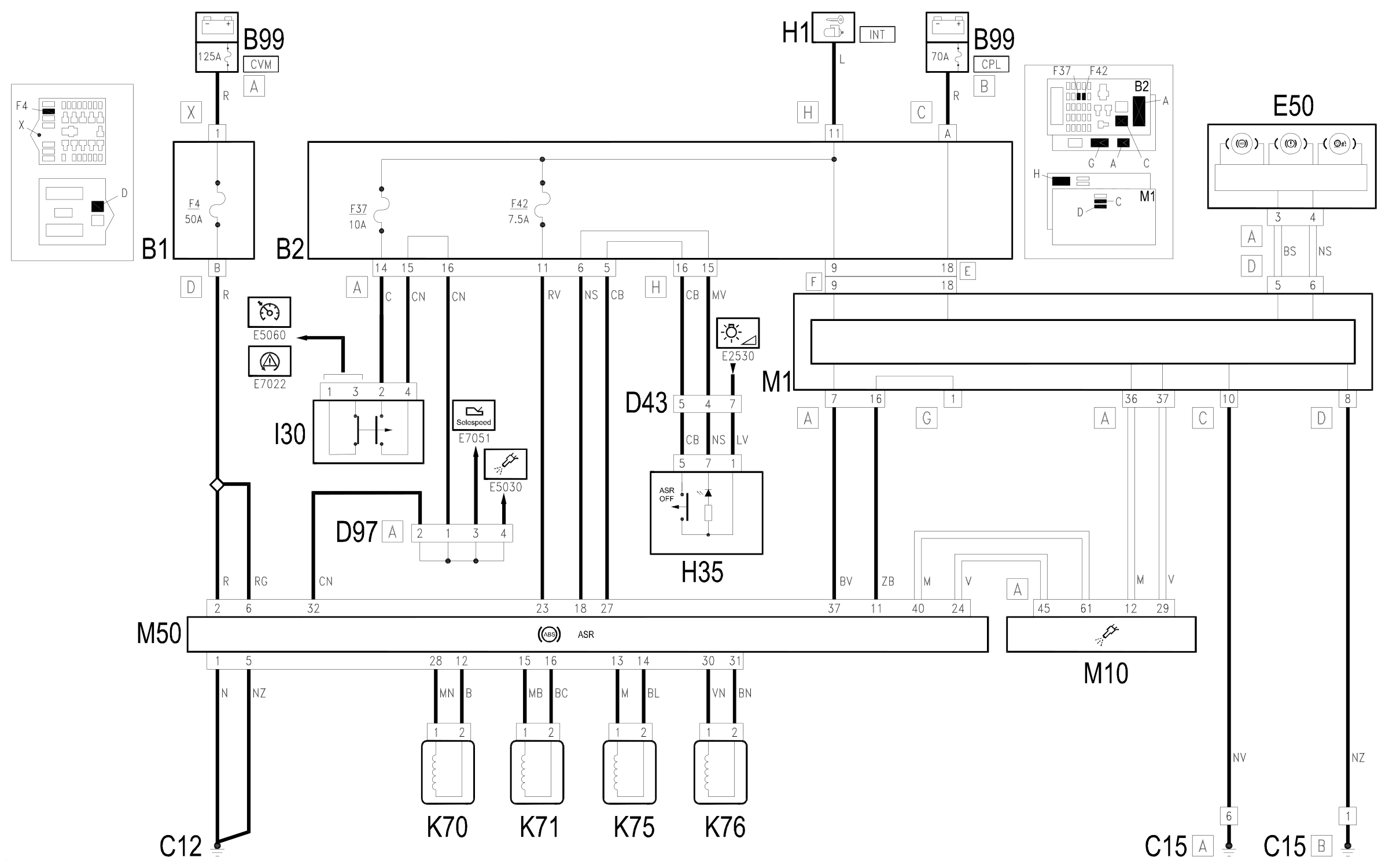
Components
| Code | Component | See |
|---|---|---|
| B01 | Engine compartment junction unit | description 5505A |
| B02 | Junction unit under dashboard | description 5505A |
| B99 | Maxifuse box on battery | description 5530B |
| C12 | ABS front earth | |
| C15 | Facia earth, driver's side | |
| D43 | Dashboard/centre console coupling | |
| D97 | Short circuiting coupling | |
| E50 | Instrument panel | description 5560B |
| H01 | Ignition switch | description 5520A |
| H35 | Switches on tunnel | description 7040L |
| K70 | Left. front wheel sensor for ABS | description 3340A |
| K71 | Right. front wheel sensor for ABS | description 3340A |
| K75 | .Left rear wheel sensor for ABS | description 3340A |
| K76 | .Right rear wheel sensor for ABS | description 3340A |
| M01 | Body computer | description 5505A |
| M10 | Engine management ECU | description 1056B |
| M50 | ABS control unit | description 3340A |
Component location
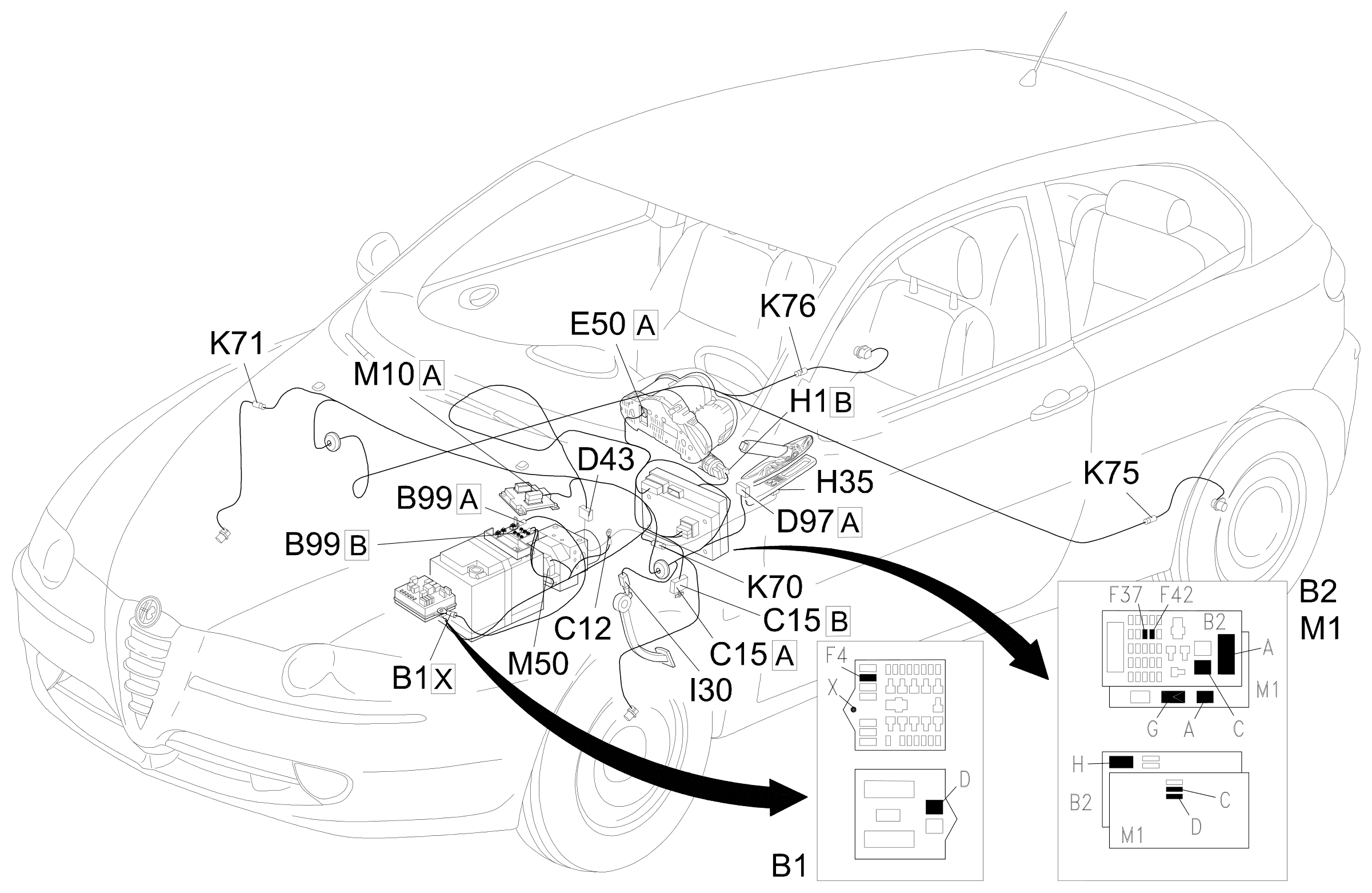
Parts & tools for this job Staging For 2000 Alfa Romeo 147
- TOOLDigital multimeterSearch: automotive digital multimeter
- PARTAssorted fuse kitSearch: car fuse assortment kit
- TOOLWire crimper and connector kitSearch: wire crimper connector kit
Links open Amazon search results in a new tab. As an Amazon Associate I earn from qualifying purchases.