
ANTI-LOCK BRAKE SYSTEM - ABS (70 - BRAKES) (page 2 of 2)
- Make
- Land Rover
- Model
- Discovery 300Tdi Discovery
- Section
- DESCRIPTION AND OPERATION
70
BRAKES
4
DESCRIPTION AND OPERATION
System description
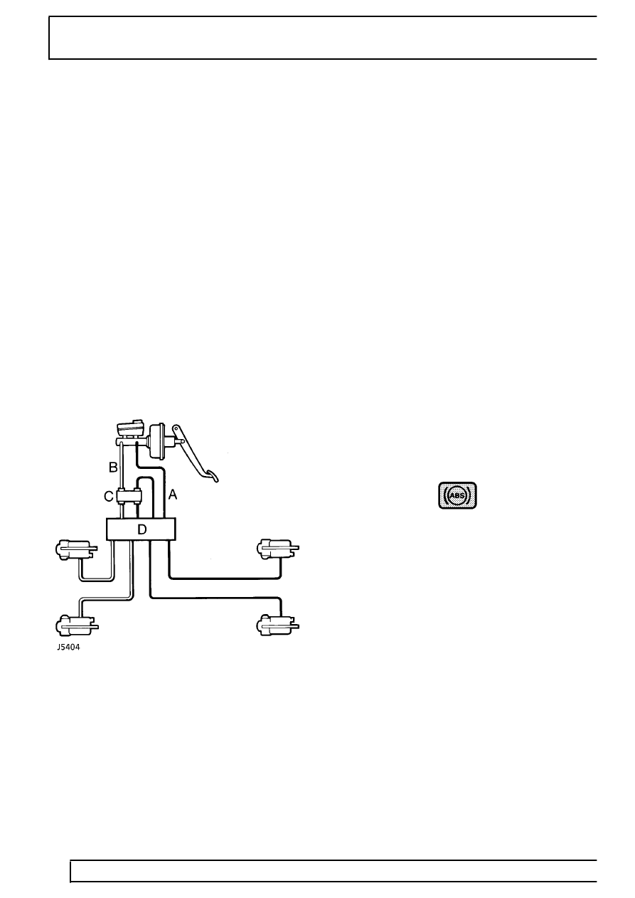
The brake system consists of dual hydraulic circuits in
a front - rear split. That is individual circuits to front
and rear axles.
Wheelspeed signals are provided by the fitting of
exciter rings to axles and speed sensors.
An ABS stop light switch is fitted to provide a braking
signal to the ECU as well as operate the stop lights.
Electrical wiring is provided as necessary with system
relays and fuses. Discovery Electrical Troubleshooting
Manual gives the location and wiring circuits of these
components.
Visual warning of system malfunction is provided via a
warning light in the instrument panel.
Hydraulic circuit ABS
Key
A = Primary hydraulic circuit
B = Secondary hydraulic circuit
C = Pressure reducing valve
D = ABS Modulator
ABS System operation
During normal braking the feel of the brake pedal on
vehicles equipped with ABS will be the same as that
on non ABS vehicles. During ABS cycling the driver
will experience feedback in the form of a pulsating
brake pedal and solenoid/pump motor noise from the
Modulator.
The system is fully automatic in operation both on and
off road, and will only act when the ECU detects that
ABS cycling is necessary. The ECU continually
monitors the operation of the system.
When starting the ABS system will go through a series
of self checks, including a check of the solenoid
valves/pump motor.
WARNING LIGHT
The warning light will be on during the self check
(1.3-2 secs). If no faults are stored in the memory the
light goes out for 0.5sec,then comes on again. It will
then remain on until the vehicle is driven faster than 7
kph/5mph. This is the only time that the light will be on
without indicating a problem.
Any faults detected by the ECU will cause the warning
light to illuminate indicating that the vehicle may not
have full ABS control.
Parts & tools for this job Staging For Land Rover Discovery
- TOOLOBD2 scanner with ABSSearch: OBD2 scanner ABS SRS
- TOOLDigital multimeterSearch: automotive digital multimeter
Links open Amazon search results in a new tab. As an Amazon Associate I earn from qualifying purchases.