
OVERHAUL (page 8 of 9)
- Make
- Land Rover
- Model
- Discovery 300Tdi Discovery
57
STEERING
8
OVERHAUL
83. Hold input shaft and rock drop arm to establish
backlash is present. Continue rocking and slowly
turn sector shaft adjusting screw clockwise.
Continue rotating adjuster screw until backlash
has almost been eliminated.
84. Refit locknut and tighten.
NOTE: It is important steering box is
centralised before any adjustments are
made.
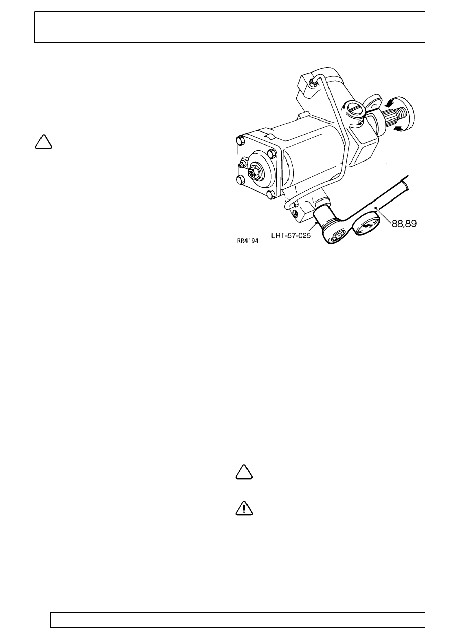
85. Check maximum rolling torque one and a quarter
turns either side of centre position, using a
torque wrench and spline socket LRT-57-025.
Rotate adjuster screw to obtain across centre
torque of 0.34 Nm plus torque figure at one and
a quarter turns. Tighten adjuster locknut to
60
Nm.
Adjusting rack adjuster.
86. Turn in rack adjuster to increase figure
measured in instruction 85. by 0.23 - 0.34 Nm.
The final figure may be less, but must not
exceed 1.35 Nm.
87. Lock rack adjuster in position with grub screw.
Tighten to
5 Nm.
Torque peak check
With input shaft rotated from lock to lock, rolling
torque figures should be greatest across centre
position and equally disposed about centre position.
The condition depends on value of shimming fitted
between valve and worm assembly inner bearing cup
and casing. The original shim washer value will give
correct torque peak position unless major components
have been replaced.
Procedure
88. With input coupling shaft toward the operator,
turn shaft fully counter-clockwise.
89. Check torque figures obtained from lock to lock
using torque wrench and spline socket
LRT-57-025.
90. Check also for equal engagement either side of
centre.
Adjustments
91. Note where greatest figures are recorded
relative to steering position.If greatest figures are
not recorded across centre of travel (steering
straight-ahead), adjust as follows:
If torque peak occurs before centre position, add to
shim washer value; if torque peak occurs after centre
position, subtract from shim washer value,
refer to
fitting valve and worm assembly .
Shim washers are available as follows:
0.03mm, 0.07mm, 0.12mm and 0.24mm.
NOTE: Adjustment of 0.07mm to shim
value will move torque peak area by 1/4
turn on the shaft.
CAUTION: When reshimming valve and
worm, extreme caution must be exercised
to prevent seal damage during
reassembly.
Parts & tools for this job Staging For Land Rover Discovery
- TOOLTie rod end toolSearch: tie rod end puller
- TOOLBall joint separatorSearch: ball joint separator
- FLUIDPower steering fluidSearch: Land Rover power steering fluid
Links open Amazon search results in a new tab. As an Amazon Associate I earn from qualifying purchases.