
Pressure pump support - r.r.
- Make
- Lancia
- Model
- Thesis Factory Service Manual
- Year
- 2002–2009
- Section
- Diesel fuel injection system › Pressure pump support - r.r.
PRESSURE PUMP SUPPORT - R.R.
Removing
- Position the vehicle on a lift.
- Open the boot and disconnect the negative battery terminal.
See in Op. 7055B54 PROTECTION/GUARD under engine - R.R.
See in Op. 4450B04 Right FRONT WHEEL (one) - R.R.
See in Op. 7055B42 FRONT WHEEL ARCH LINER (one), left or right - R.R.
See in Op. 7055B64 Engine compartment DUST SEAL in front wheel arch (one), left or right - R.R.
See in Op. 1016A10 SOUND-PROOFING COVER - R.R.
See in Op. 7040D50 ENGINE COMPARTMENT UPPER SOUND INSULATION SHIELD - R.R.
See in Op. 1048B44 RIGID air supply PIPE from heat exchanger to intake manifold - R.R.
See in Op. 1048A56 UPPER RESONATOR - R.R.
See in Op. 1092G10 Engine components single drive BELT - R.R.
See in Op. 1092G21 Engine components single belt FIXED TENSIONER - R.R. with belt removed
See in Op. 1092A10 Crankshaft PULLEY - R.R.
See in Op. 1032D12 Timing system protective COVER(S) - R.R.
See in Op. 1032B10 TOOTHED timing BELT - R.R. for timing adjustment or replacement
See in Op. 1060E30 PRESSURE PUMP drive PULLEY - R.R.
See in Op. 1060E10 PRESSURE PUMP for diesel injection - R.R.
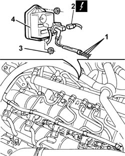
1. Disconnect the vacuum pipes from the brake servo vacuum pipe, from the pneumatic valve on the throttle casing and from the rigid section connected to the variable geometry solenoid valve.
2. Disconnect the electrical connection for the solenoid valve on the vacuum reservoir.
| Description | Connector | |
|---|---|---|
| 2 | Throttle body solenoid valve | L062 |
- Release the vacuum pipes from the retaining bands.
3. Undo the nuts fixing the vacuum reservoir to the mounting bracket.
4. Remove the vacuum reservoir.
1. Undo the bolts securing the water recirculation pipe.
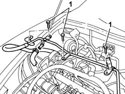
- Raise the lift.
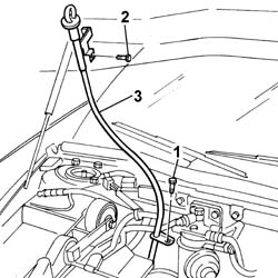
1. Undo the lower bolt securing the engine oil dipstick tube.
- Lower the lift.
2. Undo the upper bolt securing the engine oil dipstick tube.
3. Release the coupling for the engine wiring from the fastening on the pipe, then remove the engine oil dipstick pipe from the top part of the engine compartment.
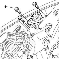
1. Undo the bolts fixing the power assisted steering pump and move it from its housing retracting it.
1. Undo the two retaining bolts (1a) and remove the power assisted steering pump guard (1b).
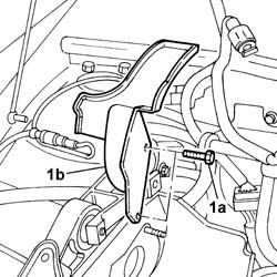
1. Undo retaining bolts (1a) and remove bracket (1b).
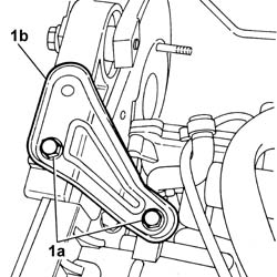
1. Undo the retaining bolts.
2. Remove the pressure pump support.
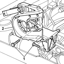
Refitting
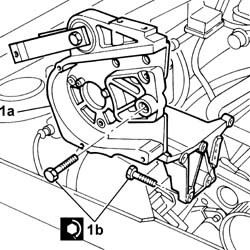
1. Fit the pressure pump support (1a) and secure it using the bolts (1b).
| Value - daNm | Fastening | Component | Ø | |
|---|---|---|---|---|
| 1b | (Cylinder block/crankcase) 2.5 | Bolt | INJECTION PRESSURE PUMP MOUNT | M8 |
- Fit the bracket joining the intake manifold and the cylinder head and tighten the fixing bolts.
- Fit the power assisted steering pump guard and tighten the retaining bolts.
1. Position the power assisted steering pump in its housing and secure it tightening the bolts to the recommended torque.
| Value - daNm | Fastening | Component | Ø | |
|---|---|---|---|---|
| 1 | 2.5 | Bolt | POWER STEERING PUMP | M8 |
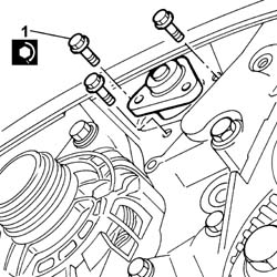
- Fit the oil dipstick pipe, raise the lift and tighten the lower fixing bolt on the oil sump.
- Lower the vehicle and tighten the upper fixing bolt.
- Press fit the engine wiring coupling on the engine oil dipstick pipe.
- Fit the rigid water recirculation pipe and connect it to the flexible sections on the head and on the thermostat.
- Tighten the bolts fixing the recirculation pipe to the intake manifold.
- Fit the vacuum reservoir and tighten the fixing nuts to the mounting bracket.
- Connect the electrical connection for the solenoid valve on the vacuum reservoir.
| Description | Connector | |
|---|---|---|
| Throttle body solenoid valve | L062 |
- Connect the vacuum pipes to the brake servo vacuum pipe, to the pneumatic valve on the throttle casing and to the rigid section connected to the variable geometry solenoid valve.
- Secure it to the engine using the plastic bands opened previously.
See in Op. 1060E10 PRESSURE PUMP for diesel injection - R.R.
See in Op. 1060E30 PRESSURE PUMP drive PULLEY - R.R.
See in Op. 1032B10 TOOTHED timing BELT - R.R. for timing adjustment or replacement
See in Op. 1032D12 Timing system protective COVER(S) - R.R.
See in Op. 1092A10 Crankshaft PULLEY - R.R.
See in Op. 1092G21 Engine components single belt FIXED TENSIONER - R.R. with belt removed
See in Op. 1092G10 Engine components single drive BELT - R.R.
See in Op. 1048A56 UPPER RESONATOR - R.R.
See in Op. 1048B44 RIGID air supply PIPE from heat exchanger to intake manifold - R.R.
See in Op. 7040D50 ENGINE COMPARTMENT UPPER SOUND INSULATION SHIELD - R.R.
See in Op. 1016A10 SOUND-PROOFING COVER - R.R.
See in Op. 7055B64 Engine compartment DUST SEAL in front wheel arch (one), left or right - R.R.
See in Op. 7055B42 FRONT WHEEL ARCH LINER (one), left or right - R.R.
See in Op. 7055B54 PROTECTION/GUARD under engine - R.R.
See in Op. 4450B04 Right FRONT WHEEL (one) - R.R.
- Top up the engine coolant, following the instructions in the description:
See in Op. 0010T21 ENGINE COOLANT - Check density and top up if necessary
- Connect the negative battery terminal.
- Remove the vehicle from the lift.
Removing
- Position the vehicle on a lift.
- Open the boot and disconnect the negative battery terminal.
See in Op. 7040D50 ENGINE COMPARTMENT UPPER SOUND INSULATION SHIELD - R.R.
See in Op. 1016A10 SOUND-PROOFING COVER - R.R.
See in Op. 7055B54 PROTECTION/GUARD under engine - R.R.
See in Op. 4450B04 Right FRONT WHEEL (one) - R.R.
See in Op. 7055B42 FRONT WHEEL ARCH LINER (one), left or right - R.R.
See in Op. 7055B64 Engine compartment DUST SEAL in front wheel arch (one), left or right - R.R.
See in Op. 1092G10 Engine components single drive BELT - R.R.
See in Op. 1032D12 Timing system protective COVER(S) - R.R.
See in Op. 1032B10 TOOTHED timing BELT - R.R. for timing adjustment or replacement
See in Op. 1060E30 PRESSURE PUMP drive PULLEY - R.R.
See in Op. 1060F20 PIPE from PRESSURE PUMP to FUEL MANIFOLD - R.R.
See in Op. 1060F34 PIPE from fuel MANIFOLD to INJEJCTOR - R.R.
See in Op. 1060E10 PRESSURE PUMP for diesel injection - R.R.
- Disconnect the negative battery terminal.
1. Disconnect the electrical connection for the throttle casing pneumatic solenoid valve.
| Description | Connector | |
|---|---|---|
| 1 | Throttle body solenoid valve | L062 |
2. Undo the fixing bolts (2a), disconnect the pipe (2b) connected to the pneumatic valve and remove the vacuum reservoir (2c).
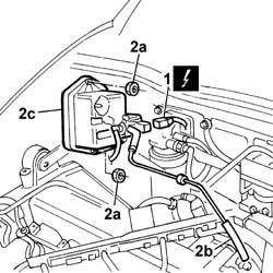
1. Undo the two fixing bolts.
2. Remove the vacuum reservoir support.
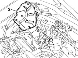
1. Undo the upper engine oil dipstick pipe fixing bolts.
2. Undo the lower engine oil dipstick pipe fixing bolts.
- Open the bands and release the electrical leads connected to it and release the timing sensor from the band.
3. Remove the engine oil dipstick pipe.
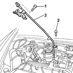
1. Undo the fixing bolts.
2. Remove the plastic protection fixed to the power assisted steering pump.
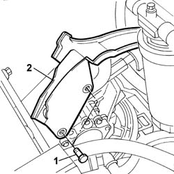
1. Undo the fixing bolts.
2. Remove the pressure pump support.
Refitting
- Fit the pressure pump support tighten the fixing bolts to torque.
| Value - daNm | Fastening | Component | Ø | |
|---|---|---|---|---|
| (Cylinder block/crankcase) 2.5 | Bolt | INJECTION PRESSURE PUMP MOUNT | M8 |
| Value - daNm | Fastening | Component | Ø | |
|---|---|---|---|---|
| (Intake manifold) 2.5 | Bolt | INJECTION PRESSURE PUMP MOUNT | M8 |
- Fit the plastic protection for the power assisted steering pump.
- Fit the engine oil dipstick pipe.
- Tighten the bolts fixing the oil dipstick pipe.
| Value - daNm | Fastening | Component | Ø | |
|---|---|---|---|---|
| 0.9 | Bolt | OIL LEVEL DIPSTICK PIPE | M6 |
- Fit the vacuum reservoir support in the housing in the pressure pump support.
- Fit the vacuum reservoir in the support and tighten the fixing bolts.
- Connect the connecting pipes to the pneumatic valve.
- Connect the electrical connection for the solenoid valve.
| Description | Connector | |
|---|---|---|
| Throttle body solenoid valve | L062 |
See in Op. 1060E10 PRESSURE PUMP for diesel injection - R.R.
See in Op. 1060F34 PIPE from fuel MANIFOLD to INJEJCTOR - R.R.
See in Op. 1060F20 PIPE from PRESSURE PUMP to FUEL MANIFOLD - R.R.
See in Op. 1060E30 PRESSURE PUMP drive PULLEY - R.R.
See in Op. 1032B10 TOOTHED timing BELT - R.R. for timing adjustment or replacement
See in Op. 1032D12 Timing system protective COVER(S) - R.R.
See in Op. 1092G10 Engine components single drive BELT - R.R.
See in Op. 7055B64 Engine compartment DUST SEAL in front wheel arch (one), left or right - R.R.
See in Op. 7055B42 FRONT WHEEL ARCH LINER (one), left or right - R.R.
See in Op. 4450B04 Right FRONT WHEEL (one) - R.R.
See in Op. 7055B54 PROTECTION/GUARD under engine - R.R.
See in Op. 7040D50 ENGINE COMPARTMENT UPPER SOUND INSULATION SHIELD - R.R.
See in Op. 1016A10 SOUND-PROOFING COVER - R.R.
- Open the boot and connect the negative battery terminal.
- Remove the vehicle from the lift.
Parts & tools for this job Staging For 2002 Lancia Thesis
- PARTGlow plugsSearch: Lancia Thesis 2002 glow plugs
- TOOLGlow plug socketSearch: glow plug socket
- TOOLDiesel compression testerSearch: diesel compression tester
Links open Amazon search results in a new tab. As an Amazon Associate I earn from qualifying purchases.