
Water pump - r + r with engine removed
- Make
- Fiat
- Model
- Ulysse Factory Service Manual
- Year
- 2002–2010
- Section
- Engine cooling › Water pump - r + r with engine removed
WATER PUMP - R + R WITH ENGINE REMOVED
Removing
- Carry out
Op. 1004D40 ENGINE - POSITION ON STAND AND REMOVE
1. Remove the tensioner roller.
2. Remove the crankshaft pulley.
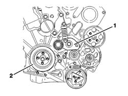
- Remove the right engine support.
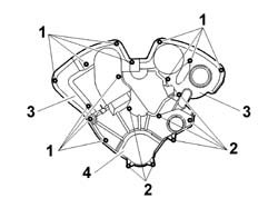
1. Loosen the bolts fixing the upper timing belt guards.
2. Loosen the bolts fixing the lower timing belt guards.
3. Remove the upper guards.
4. Remove the lower guard.
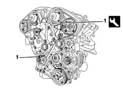
1. In order to lock the timing pullies in the correct timing position, insert the retaining tools in the special housings in the camshaft pullies and fit a pin in the crankshaft housing.
| Description | Code | Function | |
|---|---|---|---|
| 1 | Pins | 1.870.893.000 | Securing crankshaft and timing pullies |
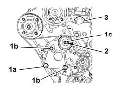
1. Undo the bolt (1a) fixing the timing belt moving tensioner, then loosen the bolts (1b) and the nut (1c) on the moving tensioner.
2. Rotate the tensioner roller cam in a clockwise direction.
3. Remove the upper winding roller, then remove the timing belt starting from the tensioner roller and the water pump.
- Release and remove the timing belt fixed tensioner.
- Remove the timing side engine support.
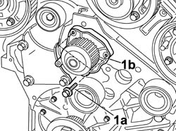
1. Undo the bolts (1a) and remove the water pump (1b).
- Separate the water pump gasket.
Refitting
- Fit the water pump with a new gasket and screw in the bolts fixing it to the crankcase without tightening them.
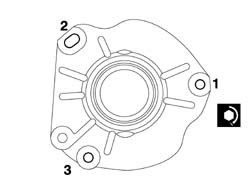
1. Tighten the water pump fixing bolts, following the procedure described below bearing in mind that the tightening order illustrated in the diagram should be followed for each stage.
- Pre-tighten the cylinder head fixing bolts to the value given in the table.
| Value daNm | Fastening | Component | Ø | |
|---|---|---|---|---|
| (-) 0.5 | Bolt | COOLANT PUMP | M |
- Tighten the bolts fixing the water pump definitively to the recommended torque.
| Value daNm | Fastening | Component | Ø | |
|---|---|---|---|---|
| (-) 0.8 | Bolt | COOLANT PUMP | M |
- Position the timing side engine support, then tighten the fixing bolts to the recommended torque.
| Value daNm | Fastening | Component | Ø | |
|---|---|---|---|---|
| (Cylinder guard side) 6 | Bolt | INTERMEDIATE POWER UNIT RIGID SUPPORT | M |
- Fit the fixed timing belt tensioner and tighten the retaining bolt to the recommended torque.
| Value daNm | Fastening | Component | Ø | |
|---|---|---|---|---|
| (Cylinder head) 8 | Bolt | FIXED TENSIONER | M |
Make sure that the camshaft pulley retaining tools are correctly inserted in their housings and that there is a pin in the crankshaft pulley housing.
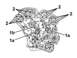
1. Check that the rollers (1a) and the water pump (1b) rotate freely and there is no clearance or hard spots.
2. Loosen the bolts fixing the camshaft pullies.
Make sure that the camshaft and crankshaft calibration is correct.
Check that the camshaft pinions rotate freely on their hub.
- Rotate the camshaft pullies in a clockwise direction until the tappets stop at the bottom.
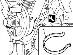
1. Attach the timing belt to the crankshaft toothed drive pulley and secure it using the retaining pin.
| Description | Code | Function | |
|---|---|---|---|
| 1 | Caliper | 1.870.900.100 | Timing belt retaining pliers |
1. Position the timing belt on the fixed tensioner (1a), then make sure that the branch (1b) of the belt is taut.
Gently rotate the camshaft pulley in the opposite direction of rotation to the direction of rotation of the engine to facilitate the fitting of the timing belt.
2. Fit the timing belt on the camshaft exhaust pulley.
The value of the angular movement of the pulley in relation to the timing belt should not exceed the width of one tooth.
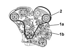
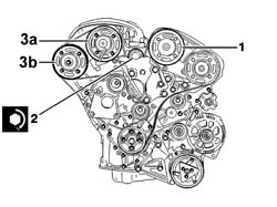
1. Fit the timing belt on the camshaft inlet pulley.
2. Position the roller on the engine and tighten the fixing bolt to the recommended torque.
| Value daNm | Fastening | Component | Ø | |
|---|---|---|---|---|
| 2 | (-) 8 | Bolt | FIXED TENSIONER | M |
3. Fit the timing belt on the inlet pulley (3a) and on the exhaust pulley (3b).
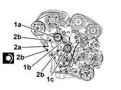
1. Fit the timing belt on the moving tensioner (1a), on the water pump pulley (1b) and on the fixed tensioner (1c).
2. Exerting a counter-force through the opening (2a) in the moving tensioner support, fit the bolts (2b) and tighten them to the recommended torque.
| Value daNm | Fastening | Component | Ø | |
|---|---|---|---|---|
| 2b | (-) 2.5 | Bolt | MOVING TIMING TENSIONER | M |
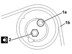
1. Exert a counter-force through the opening (1a) and tension the timing belt (1b) rotating the tensioner roller in an anti-clockwise direction until it is in the end of travel position.
2. Tighten the nut on the timing belt moving tensioner to the recommended torque.
| Value daNm | Fastening | Component | Ø | |
|---|---|---|---|---|
| 2 | (-) 1 | Bolts | MOVING TENSIONER |
1. Tighten the bolts (1a), (1b), (1c) and (1d) fixing the camshaft pullies to the recommended torque following the order illustrated in the diagram.
| Value daNm | Fastening | Component | Ø | |
|---|---|---|---|---|
| 1a | (-) 1 | Bolts | DRIVE PULLEY(PULLIES) TIMING |
| Value daNm | Fastening | Component | Ø | |
|---|---|---|---|---|
| 1b | (-) 1 | Bolts | DRIVE PULLEY(PULLIES) TIMING |
| Value daNm | Fastening | Component | Ø | |
|---|---|---|---|---|
| 1c | (-) 1 | Bolts | DRIVE PULLEY(PULLIES) TIMING |
| Value daNm | Fastening | Component | Ø | |
|---|---|---|---|---|
| 1d | (-) 1 | Bolts | DRIVE PULLEY(PULLIES) TIMING |
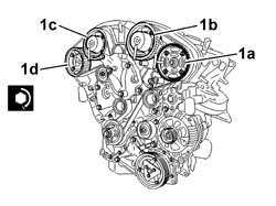
Before completing two revolutions of the crankshaft, make sure that the timing pins slide freely in their housings in the camshaft pullies. If this is not the case, loosen the bolts fixing the camshaft pullies, then position the drive pulley in such a way that the timing pins can be extracted. Tighten to the recommended torque taking care to start with the bolt furthest from the timing pin.
- Remove the timing pulley retaining tools.
| Description | Code | Function | |
|---|---|---|---|
| Pins | 1.870.893.000 | Securing crankshaft and timing pullies |
- Rotate the crankshaft throught two revolutions in its normal direction of rotation.
Never rotate in the opposite direction to the normal one.
- Position the retaining tool on the crankshaft pulley only.
| Description | Code | Function | |
|---|---|---|---|
| Pins | 1.870.893.000 | Securing crankshaft and timing pullies |
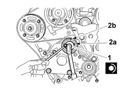
1. Loosen the nut retaining the timing belt moving tensioner.
2. Align the tensioner roller references (2a) and (2b).
- Tighten the nut on the timing belt moving tensioner loosened previously.
| Value daNm | Fastening | Component | Ø | |
|---|---|---|---|---|
| 1 | (-) 2,5 | Bolts | MOVING TENSIONER |
- Remove the retaining tool from the crankshaft pulley.
| Description | Code | Function | |
|---|---|---|---|
| Pins | 1.870.893.000 | Securing crankshaft and timing pullies |
- Rotate the crankshaft throught two revolutions in its normal direction of rotation.
Never rotate in the opposite direction to the normal one.
- Check the position of the timing belt moving tensioner.
If the references on the timing belt tensioner roller were not aligned, repeat the operation of fitting the belt.
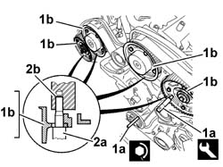
1. Fit the retaining tools (1a) in the special housings in the timing pullies (1b).
| Description | Code | Function | |
|---|---|---|---|
| Pins | 1.870.893.000 | Securing crankshaft and timing pullies |
2. Check that the references (2a) for the adjustment of the camshafts engage freely in the heads (2b) until they are in contact with the camshaft pinions.
If this is not the case, start the operation of fitting the belt again.
- Remove the timing pulley retaining tools.
| Description | Code | Function | |
|---|---|---|---|
| Pins | 1.870.893.000 | Securing crankshaft and timing pullies |
Apply FRENETANCH thread-locking agent or a similar product to the auxiliary drive pulley fixing bolts.
- Tighten the bolts fixing the auxiliary shaft drive pulley to the recommended torque.
| Value daNm | Fastening | Component | Ø | |
|---|---|---|---|---|
| 2 | (-) 1 | Bolts | MOVING TENSIONER |
- Fit the timing belt covers and tighten the fixing bolts.
- Complete with
Parts & tools for this job Staging For 2002 Fiat Ulysse
- PARTEngine gasket setSearch: Fiat Ulysse 2002 engine gasket set
- TOOLTorque wrenchSearch: 3/8 inch torque wrench
- TOOLFeeler gauge setSearch: feeler gauge set
Links open Amazon search results in a new tab. As an Amazon Associate I earn from qualifying purchases.