
Engine - position on stand and remove
- Make
- Fiat
- Model
- Ulysse Factory Service Manual
- Year
- 2002–2010
- Section
- Engine and power unit › Engine - position on stand and remove
ENGINE - POSITION ON STAND AND REMOVE
Dismantling
Position the engine on a suitable workbench.
Support the engine to prevent accidental tipping over.
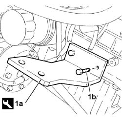
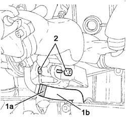
1. Position tool (1a) on the engine block beside the heat exchanger and tighten the bolts (1b).
| Description | Code | Function | |
|---|---|---|---|
| 1a | Brackets | 1.861.001.040 | Engine overhaul stand support |
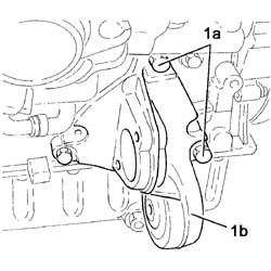
1. Undo the bolts (1a) and remove the intermediate driveshaft support (1b).
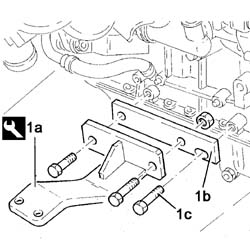
- Prepare an adaptor plate as shown in the drawing in the following figure
1. Fit tool (1a), interposing bracket (1b) made previously, and tighten bolts (1c).
| Description | Code | Function | |
|---|---|---|---|
| 1a | Brackets | 1.861.001.040 | Engine overhaul stand support |
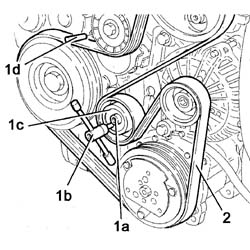
1. Loosen bolt (1a) and use a box wrench (1b) of appropriate size to turn the cam tensioner (1c) anticlockwise until the 4 mm dia pin (1d) fits into the reference hole on the tensioner.
2. Release and remove the auxiliary shaft drive belt.
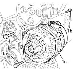
1. Undo front bolts (1a) and rear bolts (1b) and remove alternator (1c).
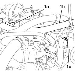
1. Unscrew bolts (1a) securing the exhaust gas recovery pipe (1b) for the EGR.
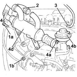
1. Unscrew the remaining nut (1a) and nut (1b) securing exhaust gas recovery pipe (1c) for EGR.
2. Loosen the band and disconnect the coolant inlet pipe from the heat exchanger for the EGR system.
3. Disconnect the vacuum pipe from the EGR valve.
4. Unscrew nuts (4a) and remove EGR valve (4b) complete with pipe (4c) and heat exchanger (4d).
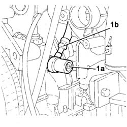
1. Undo the connector (1a) and disconnect the oil supply pipe to the turbocharger (1b) from the crankcase.
1. Loosen collar (1a) and disconnect sump oil return pipe (1b) from the turbocharger (1b), turbo side.
2. Undo the bolt fixing the turbocharger to the mounting bracket.
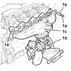
1. Unscrew nuts (1a) with spacers (1b) then remove the exhaust manifold (1c) with turbocharger (1d) and gasket (1e).
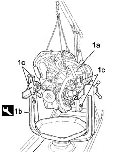
1. Use a hydraulic lift (1a) to anchor the attachment points and position on an overhaul stand (1b), securing with bolts of appropriate size (1c).
| Description | Code | Function | |
|---|---|---|---|
| 1a | Overhaul stand | 1.861.000.000 | Engine mount |
Reassembly
- Anchor the engine to the attachment points, ensuring that all the cables are under tension and do not bind.
- Undo the fixing bolts and remove the engine from the overhaul stand.
| Description | Code | Function | |
|---|---|---|---|
| Overhaul stand | 1.861.000.000 | Engine mount |
- Position the engine on a suitable workbench.
Support the engine to prevent accidental tipping over.
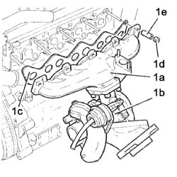
1 Fit exhaust manifold (1a) with turbocharger (1b) and gasket (1c) then tighten nuts (1d) with spacers (1e) and tighten to the specified torque.
| Value daNm | Fastening | Component | dia | |
|---|---|---|---|---|
| 1d | (-) | Nuts | TURBOCHARGER - EXHAUST MANIFOLD - HOSE CONNECTED TO EXHAUST PIPE - R.R. |
1. Tighten the turbocharger bolt to the bracket and tighten to the specified torque.
| Value daNm | Fastening | Component | dia | |
|---|---|---|---|---|
| 1 | 3.0 | Bolt | TURBOCHARGER - EXHAUST MANIFOLD - HOSE CONNECTED TO EXHAUST PIPE - R.R. |
2. Connect the oil return pipe to the sump (2a) to the turbocharger and tighten collar (2b).
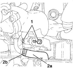
2. Connect the oil return pipe to the sump (2a) to the turbocharger and tighten collar (2b).
| Value daNm | Fastening | Component | dia | |
|---|---|---|---|---|
| 1b | 4.5 | Connector | ENGINE - Position on stand and remove |
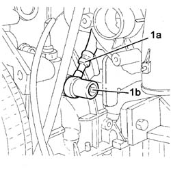
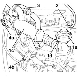
1. Fit EGR valve (1a) with pipe (1b), heat exchanger (1c) and secure by tightening nuts (1d) to the specified torque.
| Value daNm | Fastening | Component | dia | |
|---|---|---|---|---|
| 1d | 3.0 | Nuts | EXHAUST GAS/WATER HEAT EXCHANGER FOR E.G.R. system - R.R. |
2. Connect the vacuum pipe to the EGR valve.
3. Connect the coolant supply pipe to the EGR heat exchanger and tighten the band.
4. tighten the bolt (4a) and nut (4b) securing exhaust gas recovery pipe for EGR.
- Then tighten the remaining bolts securing the EGR exhaust gas recovery pipe.
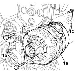
1. Position the alternator (1a), screw in bolts (1b) and (1c) then tighten to the specified torque.
| Value daNm | Fastening | Component | dia | |
|---|---|---|---|---|
| 1d | 4.1 | Bolts | ALTERNATOR - R.R. |
| Value daNm | Fastening | Component | dia | |
|---|---|---|---|---|
| 1c | 3.9 | Bolts | ALTERNATOR - R.R. |
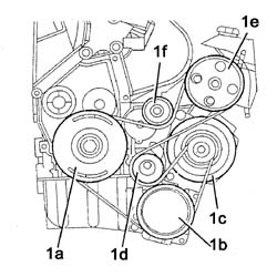
Fit a new auxiliary drivebelt to the pulleys in accordance with the layout in the figure, finishing with the mobile tensioner:
- (1a) crankshaft pulley
- (1b) air conditioner compressor pulley
- (1c) alternator pulley
- (1d) cam roller
- (1e) power steering pump pulley
- (1f) mobile tensioner roller
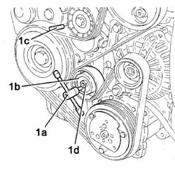
1. Use an appropriate box wrench (1a) to turn the cam tensioner (1b) until the reference pin (1c) can be withdrawn, then tighten bolt (1d) to the specified torque without altering the cam roller position.
| Value daNm | Fastening | Component | dia | |
|---|---|---|---|---|
| 1b | 4.5 | Bolts | Engine component single belt FIXED TENSIONER - R&R with belt removed |
Check that the belt is correctly positioned in the pulley grooves. Turn the engine through 4 revolutions. Check that the references align using a 2 mm dia. pin (1c) that must be able to enter the hole where the 4 mm dia. pin was positioned previously. Otherwise, repeat the adjustment operation.
- Unscrew the bolts and remove the brackets and adaptor plate used to anchor the engine to the overhaul stand from the engine block.
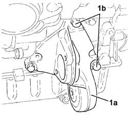
1. Fit intermediate drive shaft mount (1a) and secure by means of bolts (1b).
| Value daNm | Fastening | Component | dia | |
|---|---|---|---|---|
| 1b | 4.5 | Bolts | BEARING MOUNT for intermediate driveshaft - R&R |
Parts & tools for this job Staging For 2002 Fiat Ulysse
- PARTEngine gasket setSearch: Fiat Ulysse 2002 engine gasket set
- TOOLTorque wrenchSearch: 3/8 inch torque wrench
- TOOLFeeler gauge setSearch: feeler gauge set
Links open Amazon search results in a new tab. As an Amazon Associate I earn from qualifying purchases.