
Thermostat unit - r+r
- Make
- Fiat
- Model
- Ulysse Factory Service Manual
- Year
- 2002–2010
- Section
- Engine cooling › Thermostat unit - r+r
THERMOSTAT UNIT - R+R
Removing
- Position the vehicle on the lift.
- Disconnect the negative battery terminal.
| Description | Connector | |
|---|---|---|
| Battery |
Op. 7055B54 UNDER ENGINE PROTECTION/GUARD - R.R.
Op. 5010B18 HEATING VENTILATION UNIT AIR INTAKE - R+R
Op. 5050B34 WINDSCREEN WIPER ARM/S COMPLETE WITH BLADE - R+R
Op. 7210E22 R.R. WINDSCREEN BASE TRIM
Op. 1016A42 LEFT HAND CYLINDER HEAD IGNITION COIL COVER - R+R
Op. 1048A47 SLEEVE FROM RIGID PIPE TO THROTTLE BODY - R R
See descriptions
See descriptions
1. Remove the retaining bands (1a) and disconnect the pipe (1b) from the radiator to the thermostat casing.
| Description | Code | Function | |
|---|---|---|---|
| Caliper | Band opening |
2. Loosen the retaining band (2a) and disconnect the pipe (2b) from the thermostat casing to the engine oil heat exchanger.
| Description | Code | Function | |
|---|---|---|---|
| 2a | Caliper | Band opening |
3. Undo the fixing bolt (3a) and detach the pipe mounting bracket (3b).
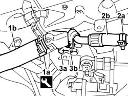
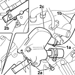
1. Loosen the retaining band (1a) and disconnect the pipe (1b) from the thermostat casing to the engine oil heat exchanger.
| Description | Code | Function | |
|---|---|---|---|
| 1a | Caliper | Band opening |
2. Undo the fixing bolts (2a) and (2b) then remove the thermostat casing (2c) from the crankcase.
Refitting
1. At the bench, extract the bulb (1a) from the thermostat casing and replace the seal (1b).
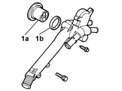
- Fit the bulb in the thermostat casing.
- Place the thermostat casing in the housing.
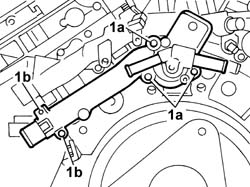
1. Tighten the fixing bolts (1a) and the bolts (1b) fixing the thermostat casing to the crankcase to the recommended torque.
| Value - daNm | Fastening | Component | Ø | |
|---|---|---|---|---|
| 1a | 2.5 | Bolts | THERMOSTAT UNIT |
| Value - daNm | Fastening | Component | Ø | |
|---|---|---|---|---|
| 1b | 0.8 | Bolts | THERMOSTAT UNIT |
- Connect the pipe from the thermostat casing to the automatic transmission fluid heat exchanger and tighten the retaining band.
| Description | Code | Function | |
|---|---|---|---|
| Caliper | Band opening |
- Connect the pipe from the thermostat casing to the engine oil heat exchanger and tighten the retaining band.
| Description | Code | Function | |
|---|---|---|---|
| Caliper | Band opening |
- Position the pipe mounting bracket and tighten the fixing bolt.
- Connect the pipe from the radiator to the thermostat casing and renew the retaining band.
| Description | Code | Function | |
|---|---|---|---|
| Caliper | Band opening |
See descriptions
See descriptions
Op. 1048A47 SLEEVE FROM RIGID PIPE TO THROTTLE BODY - R R
Op. 1016A42 LEFT HAND CYLINDER HEAD IGNITION COIL COVER - R+R
Op. 7210E22 R.R. WINDSCREEN BASE TRIM
Op. 5050B34 WINDSCREEN WIPER ARM/S COMPLETE WITH BLADE - R+R
Op. 5010B18 HEATING VENTILATION UNIT AIR INTAKE - R+R
Op. 7055B54 UNDER ENGINE PROTECTION/GUARD - R.R.
- Connect the negative battery terminal.
| Description | Connector | |
|---|---|---|
| Battery |
Op. 0010T20 ENGINE COOLANT - CHANGE
- Remove the vehicle from the lift.
Removing
Op. 5530B56 BATTERY DRIP TRAY COVER - R.R.
- Disconnect the negative battery terminal.
Op. 5010B18 HEATING VENTILATION UNIT AIR INTAKE - R+R
See descriptions
See descriptions
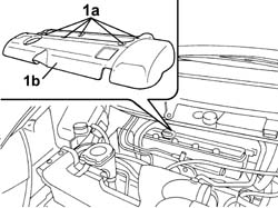
- Rotate the fastening pins (1a) through 90° and remove the coil cover (1b).
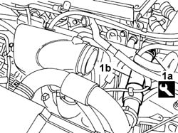
- Act on the retaining band (1a) using the tool and release the coolant outlet hose (1b) from the thermostat assembly.
| Description | Code | Function | |
|---|---|---|---|
| Caliper | Removing bands |
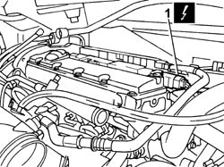
- Disconnect the electrical connection from the coils.
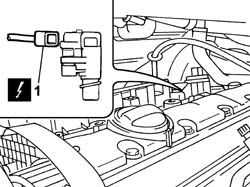
- Disconnect the electrical connection for the cam angle sensor.
- Disconnect the rapid connector (1a) from the cut out valve and move the hose (1b) aside.
- Undo the fixing bolts (2a) and remove the cut out valve (2c).
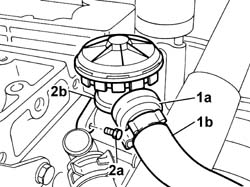
- Remove the fastening band (1a) using the special tool and move the hose (1b) aside.
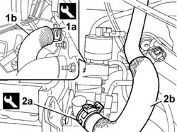
- Remove the fastening band (2a) using the special tool and release the hose (1b).
| Description | Code | Function | |
|---|---|---|---|
| Caliper | Removing bands |
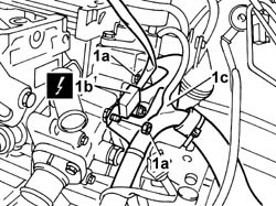
- Undo the fixing nuts (1a), move the condenser (1b) aside and move the mounting bracket complete with wiring (1c) aside.
- Disconnect the electrical connection for the E.G.R. solenoid valve.
- Disconnect the electrical connection for the water temperature sensor.
- Disconnect the electrical connection for the rpm sensor.
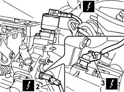
- Undo the fixing nuts and bolts (1a) and remove the thermostat unit (1b).
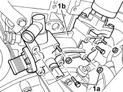
- At the bench, separate the E.G.R. system solenoid valve from the thermostat unit.
Refitting
- At the bench, connect the E.G.R. solenoid valve to the thermostat unit.
- Fit the thermostat unit and tighten the fixing bolts.
- Connect the electrical connection for the rpm sensor.
- Connect the electrical connection for the coolant temperature sensor.
- Connect the electrical connection for the E.G.R. solenoid valve.
- Fit the mounting bracket complete with wiring, fit the condenser and tighten the fixing bolts.
- Fit the hose and restore the fastening using the tool.
| Description | Code | Function | |
|---|---|---|---|
| Caliper | Removing bands |
- Fit the hose and restore the fastening using the tool.
| Description | Code | Function | |
|---|---|---|---|
| Caliper | Release the bands |
- Fit the cut out valve and tighten the fixing bolts.
- Connect the rapid connector for the hose to the cut out valve.
- Connect the electrical connection for the cam angle sensor.
- Connect the electrical connection for the coils.
- Fit the coolant outlet hose to the thermostat unit and restore the fastening using the tool.
| Description | Code | Function | |
|---|---|---|---|
| Caliper | Removing bands |
- Fit the coil cover and renew the fastenings.
- Connect the negative battery terminal.
Op. 5530B56 BATTERY DRIP TRAY COVER - R.R.
See descriptions
See descriptions
Op. 5010B18 HEATING VENTILATION UNIT AIR INTAKE - R+R
Removing
See
Op. 5530B56 BATTERY DRIP TRAY COVER - R.R.
See
Op. 5010B18 CLIMATE CONTROL UNIT AIR INTAKE - R.R.
See
Op. 5050B34 WINDSCREEN WIPER ARM/S COMPLETE WITH BLADE - R+R
Both
See
Op. 7055A18 L/H OR R/H SIDE RUBBING STRIP (ONE) FOR FRONT DOOR - R+R
See
Op. 5050B38 WINDSCREEN WIPER ASSEMBLY - R+R OR REPAIR
See
Op. 1048A10 AIR FILTER ASSEMBLY - R.R.
See
Op. 1080C54 EXHAUST GAS SUPPLY PIPE FROM E.G.R. VALVE TO INTAKE MANIFOLD - R.R.
See
Op. 1048A44 HOSE FROM FILTER TO TURBOCHARGER AIR INLET PIPE - REPLACE
See
Op. 1048A50 TURBOCHARGER AIR INTAKE PIPE - R.R.
See
Op. 1088D22 WATER PUMP INLET CONNECTOR - R.R.
1. Disconnect the electrical connection for the glow plug wiring.
2. Disconnect the electrical connection for the engine coolant temperature sensor.
3. Disconnect electrical connection (3a), disconnect vacuum pipe (3b) and unscrew bolts (3c), remove intake manifold actuator control solenoid.
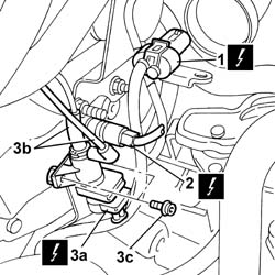
1. Open the securing band (1a) using special pliers and destructive band (1b).
2. Remove the oil vapour pipe.
| Description | Code | Function | |
|---|---|---|---|
| Caliper | Open the retaining bands |
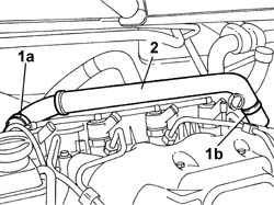
1. Open bands (1a), disconnect oil vapour pipe (1b) and move out of the working area.
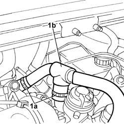
Position a suitable container for collecting the coolant.
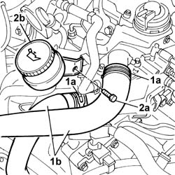
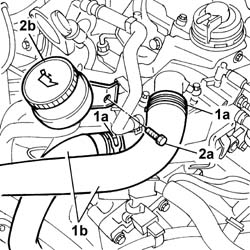
1. Open bands (1a) using special pliers, move coolant sleeves (1b) out of the working area and recover the coolant.
2. Undo bolt (2a) ande move the oil dipstick (2b) aside.
| Description | Code | Function | |
|---|---|---|---|
| Caliper | Open the retaining bands |
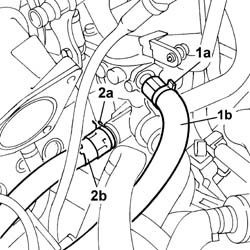
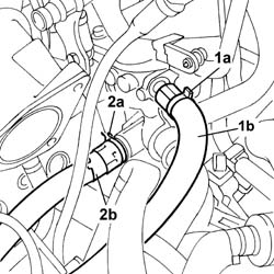
1. Open the securing band (1a) using special pliers and move aside pipe (1b).
2. Undo clip (2a) and disconnect pipe (2b) from the thermostat.
| Description | Code | Function | |
|---|---|---|---|
| Caliper | Open the retaining bands |
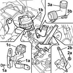
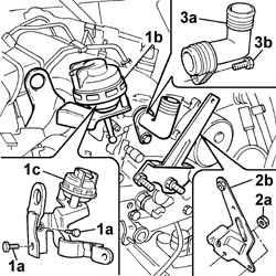
1. Undo bolts (1a), release head (1b) and remove Swirl valve (1c).
2. Undo nuts (2a), remove the mounting bracket (2b) and release from clips.
3. Undo bolt (3a) and remove the fitting (3b).
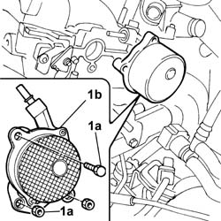
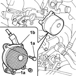
1. Undo bolt and nuts (1a) and remove the vacuum pump (1b).
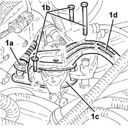
1. Disconnect the gear selector flexible cable (1a), undo the bolts (1b) and remove the bracket (1c) complete with counter-weight (1d).
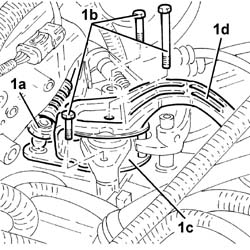
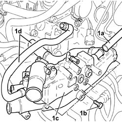
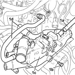
1. Disconnect pipe (1a), undo the bolts (1b) and remove the thermostat (1c) complete with pipes (1d).
Refitting
Place the thermostat unit in position, connect the pipes and tighten the fixing bolts.
| da Nm | Fastening | Component | dia |
|---|---|---|---|
| 1.0 | Bolt pretightening | FASTENING THE THERMOSTAT UNIT |
| da Nm | Fastening | Component | dia |
|---|---|---|---|
| 2.5 | Bolt tightening | FASTENING THE THERMOSTAT UNIT |
Fit the bracket, complete with counter-weight tighten the fixing bolts and connect the flexible gear selector cable.
Fit the vacuum pump in place and tighten the fixing bolts.
| da Nm | Fastening | Component | dia |
|---|---|---|---|
| 2.0 | Bolt | VACUUM UNIT |
| da Nm | Fastening | Component | dia |
|---|---|---|---|
| 2.0 | Nut | VACUUM UNIT |
Place the rigid oil filler in position and tighten the fixing bolt.
Fit the mounting bracket and tighten the fixing bolts.
Fit the swirl valve securing the ball joint to the housing.
Connect the coolant supply and return pipes to the thermostat and restore the fastening bands.
| Description | Code | Function | |
|---|---|---|---|
| Caliper | Open the retaining bands |
Fit the engine oil filler fitting and tighten the fixing bolts.
Fit the oil vapour pipes and renew the retaining bands.
| Description | Code | Function | |
|---|---|---|---|
| Caliper | Open the retaining bands |
Fit the intake manifold actuator solenoid valve, tighten the fixing bolts and connect the electrical connection.
Fit the vacuum intake pipes to the solenoid valve.
Connect the electrical connection for the coolant temperature sensor.
Connect the glow plug wiring control unit.
See
Op. 1088D22 WATER PUMP INLET CONNECTOR - R.R.
See
Op. 1048A50 TURBOCHARGER AIR INTAKE PIPE - R.R.
See
Op. 1048A44 HOSE FROM FILTER TO TURBOCHARGER AIR INLET PIPE - REPLACE
See
Op. 1080C54 EXHAUST GAS SUPPLY PIPE FROM E.G.R. VALVE TO INTAKE MANIFOLD - R.R.
See
Op. 1048A10 AIR FILTER ASSEMBLY - R.R.
See
Op. 5050B38 WINDSCREEN WIPER ASSEMBLY - R+R OR REPAIR
See
Op. 7055A18 L/H OR R/H SIDE RUBBING STRIP (ONE) FOR FRONT DOOR - R+R
See
Op. 5050B34 WINDSCREEN WIPER ARM/S COMPLETE WITH BLADE - R+R
Both
See
Op. 5010B18 CLIMATE CONTROL UNIT AIR INTAKE - R.R.
See
Op. 5530B56 BATTERY DRIP TRAY COVER - R.R.
See
Op. 0010T21 ENGINE COOLANT - CHECK DENSITY AND CHANGE, IF NECESSARY
Removing
See
Op. 5530B56 BATTERY DRIP TRAY COVER - R.R.
See
Op. 5010B18 CLIMATE CONTROL UNIT AIR INTAKE - R.R.
See
Op. 5050B34 WINDSCREEN WIPER ARM/S COMPLETE WITH BLADE - R+R
Both
See
Op. 7055A18 L/H OR R/H SIDE RUBBING STRIP (ONE) FOR FRONT DOOR - R+R
See
Op. 5050B38 WINDSCREEN WIPER ASSEMBLY - R+R OR REPAIR
See
Op. 1048A10 AIR FILTER ASSEMBLY - R.R.
See
Op. 1080C54 EXHAUST GAS SUPPLY PIPE FROM E.G.R. VALVE TO INTAKE MANIFOLD - R.R.
See
Op. 1048A44 HOSE FROM FILTER TO TURBOCHARGER AIR INLET PIPE - REPLACE
See
Op. 1048A50 TURBOCHARGER AIR INTAKE PIPE - R.R.
1. Disconnect the electrical connection for the glow plug wiring.
2. Disconnect the electrical connection for the engine coolant temperature sensor.
3. Disconnect electrical connection (3a), disconnect vacuum pipe (3b) and unscrew bolts (3c), remove intake manifold actuator control solenoid.
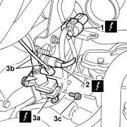
1. Open the securing band (1a) using special pliers and destructive band (1b).
2. Remove the oil vapour pipe.
| Description | Code | Function | |
|---|---|---|---|
| Caliper | Open the retaining bands |
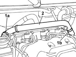
1. Open bands (1a), disconnect oil vapour pipe (1b) and move out of the working area.
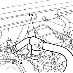
Position a suitable container for collecting the coolant.
1. Open bands (1a) using special pliers, move coolant sleeves (1b) out of the working area and recover the coolant.
2. Undo bolt (2a) ande move the oil dipstick (2b) aside.
| Description | Code | Function | |
|---|---|---|---|
| Caliper | Open the retaining bands |
1. Open the securing band (1a) using special pliers and move aside pipe (1b).
2. Undo clip (2a) and disconnect pipe (2b) from the thermostat.
| Description | Code | Function | |
|---|---|---|---|
| Caliper | Open the retaining bands |
1. Undo bolts (1a), release head (1b) and remove Swirl valve (1c).
2. Undo nuts (2a), remove the mounting bracket (2b) and release from clips.
3. Undo bolt (3a) and remove the fitting (3b).
1. Undo bolt and nuts (1a) and remove the vacuum pump (1b).
1. Disconnect the gear selector flexible cable (1a), undo the bolts (1b) and remove the bracket (1c) complete with counter-weight (1d).
1. Disconnect pipe (1a), undo the bolts (1b) and remove the thermostat (1c) complete with pipes (1d).
Refitting
Place the thermostat unit in position, connect the pipes and tighten the fixing bolts.
| da Nm | Fastening | Component | dia |
|---|---|---|---|
| 1.0 | Bolt pretightening | FASTENING THE THERMOSTAT UNIT |
| da Nm | Fastening | Component | dia |
|---|---|---|---|
| 2.5 | Bolt tightening | FASTENING THE THERMOSTAT UNIT |
Fit the bracket, complete with counter-weight tighten the fixing bolts and connect the flexible gear selector cable.
Fit the vacuum pump in place and tighten the fixing bolts.
| da Nm | Fastening | Component | dia |
|---|---|---|---|
| 2.0 | Bolt | VACUUM UNIT |
| da Nm | Fastening | Component | dia |
|---|---|---|---|
| 2.0 | Nut | VACUUM UNIT |
Place the rigid oil filler in position and tighten the fixing bolt.
Fit the mounting bracket and tighten the fixing bolts.
Fit the swirl valve securing the ball joint to the housing.
Connect the coolant supply and return pipes to the thermostat and restore the fastening bands.
| Description | Code | Function | |
|---|---|---|---|
| Caliper | Open the retaining bands |
Fit the engine oil filler fitting and tighten the fixing bolts.
Fit the oil vapour pipes and renew the retaining bands.
| Description | Code | Function | |
|---|---|---|---|
| Caliper | Open the retaining bands |
Fit the intake manifold actuator solenoid valve, tighten the fixing bolts and connect the electrical connection.
Fit the vacuum intake pipes to the solenoid valve.
Connect the electrical connection for the coolant temperature sensor.
Connect the glow plug wiring control unit.
See
Op. 1088D22 WATER PUMP INLET CONNECTOR - R.R.
See
Op. 1048A50 TURBOCHARGER AIR INTAKE PIPE - R.R.
See
Op. 1048A44 HOSE FROM FILTER TO TURBOCHARGER AIR INLET PIPE - REPLACE
See
Op. 1080C54 EXHAUST GAS SUPPLY PIPE FROM E.G.R. VALVE TO INTAKE MANIFOLD - R.R.
See
Op. 1048A10 AIR FILTER ASSEMBLY - R.R.
See
Op. 5050B38 WINDSCREEN WIPER ASSEMBLY - R+R OR REPAIR
See
Op. 7055A18 L/H OR R/H SIDE RUBBING STRIP (ONE) FOR FRONT DOOR - R+R
See
Op. 5050B34 WINDSCREEN WIPER ARM/S COMPLETE WITH BLADE - R+R
Both
See
Op. 5010B18 CLIMATE CONTROL UNIT AIR INTAKE - R.R.
See
Op. 5530B56 BATTERY DRIP TRAY COVER - R.R.
See
Op. 0010T21 ENGINE COOLANT - CHECK DENSITY AND CHANGE, IF NECESSARY
Parts & tools for this job Staging For 2002 Fiat Ulysse
- FLUIDCoolantSearch: Fiat coolant antifreeze
- PARTThermostatSearch: Fiat Ulysse 2002 thermostat
- TOOLCooling system pressure testerSearch: cooling system pressure tester
Links open Amazon search results in a new tab. As an Amazon Associate I earn from qualifying purchases.