
Single cylinder head, removed - overhaul
- Make
- Fiat
- Model
- Panda Factory Service Manual
- Year
- 2003–2012
- Section
- Cylinder head/s › Single cylinder head, removed - overhaul
SINGLE CYLINDER HEAD, REMOVED - OVERHAUL
Removing
Refitting
Removing
Op. 1048A10 AIR CLEANER FILTERING ELEMENT - REPLACE
Op. 7055B54 UNDER-ENGINE GUARD - R R
Op. 5530B56 BATTERY DRIP TRAY COVER - R.R.
Op. 5530B52 BATTERY DRIP TRAY/SUPPORT - R.R.
Position a suitable container for collecting the coolant.
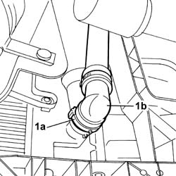
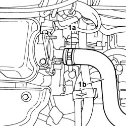
1. Working on the fastening clip (1a) disconnect the lower radiator hose (1b) and drain the system.
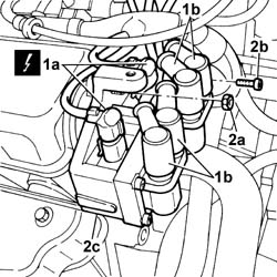
1. Disconnect the electrical connections for the ignition coils (1a) and the electrical connections for the spark plugs (1b).
| Description | Connector | |
|---|---|---|
| 1a | Ignition coil | A30A |
| Description | Connector | |
|---|---|---|
| 1a | Ignition coil | A30B |
2. Undo the fixing nuts (2a) and the bolt (2b) and remove the ignition coil assembly (2c) complete with support.
1. Open the retaining band (1a) and release the coolant pipe (1b) from the thermostat.
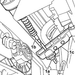
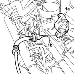
1. Working from the throttle casing control (1a), disconnect the accelerator control cable (1b).
Remove the cable from the mounting bracket.
Op. 1056B50 COOLANT TEMPERATURE SENSOR - R + R
Op. 5510C30 ENGINE TIMING SENSOR - R+R
Op. 1080D22 OIL VAPOUR PIPE FROM CAM COVER TO INTAKE R R
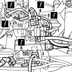
1. Disconnect the rapid connector for the fuel vapour recovery pipe.
2. Disconnect the fuel supply pipe rapid connector.
3. Open the fastening band and disconnect the single-acting valve pipe.
4. Disconnect the electrical connection for the built-in air temperature sensor.
| Description | Connector | |
|---|---|---|
| 4 | Integrated air temperature sensor | K43 |
5. Disconnect the electrical connection for the fuel vapour recovery solenoid valve.
| Description | Connector | |
|---|---|---|
| 5 | Fuel vapour recovery solenoid valve | L10 |
6. Disconnect the electrical connection for the throttle position sensor.
| Description | Connector | |
|---|---|---|
| 6 | Throttle position sensor | K56 |
7. Disconnect the electrical connection for the engine idle actuator.
| Description | Connector | |
|---|---|---|
| 7 | Idle actuator | N74 |
8. Disconnect the electrical connections for the injectors.
| Description | Connector | |
|---|---|---|
| 8 | Injector | N70A |
| Description | Connector | |
|---|---|---|
| 8 | Injector | N70B |
| Description | Connector | |
|---|---|---|
| 8 | Injector | N70C |
| Description | Connector | |
|---|---|---|
| 8 | Injector | N70D |
Move the electrical wiring aside releasing the cable duct from the fastenings on the tappet cover.
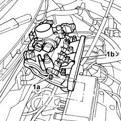
1. Undo the fixing nuts (1a) and remove the intake manifold (1b) complete with throttle body and single fuel manifold pipe.
Position a suitable container for collecting the engine oil.
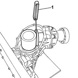
Unscrew the engine oil sump plug and drain the lubrication system.
Op. 1072C44 EXHAUST MANIFOLD HEAT SHIELD ON BULKHEAD - R+R
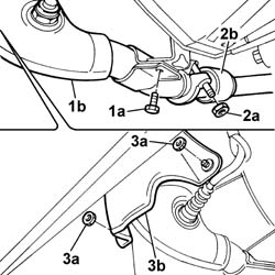
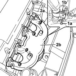
1. Undo the fixing bolt (1a) and release the bracket (1b).
2. Undo the fixing nuts (2a) and release the exhaust manifold (2b) from the cylinder head studs.
Remove the engine oil filler cap.
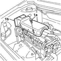
1. Undo the fixing bolts (1a) and remove the tappet cover (1b).
Remove the underlying gasket.
Op. 4450B04 RIGHT FRONT WHEEL R R
Op. 1092B60 ALTERNATOR DRIVE BELT - R + R
Op. 1092A10 CRANKSHAFT SERVICES PULLEY - R.R.
Op. 1032D12 TIMING SYSTEM PROTECTIVE COVER(S) - R + R
Op. 7055A42 FRONT GRILLE - R+R
Op. 1032B10 TOOTHED TIMING BELT - R + R FOR TIMING ADJUSTMENT OR REPLACEMENT
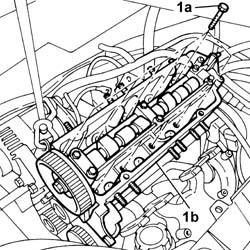
1. Undo the fixing bolts (1a) and remove the single cylinder head (1b).
Remove the underlying gasket.
Refitting
Clean the contact surfaces between the cylinder head and engine block.
Position the cylinder head gasket with the wording "ALTO" [TOP] facing the operator.
Because the gasket is made out of special material, it undergoes a polymerisation process during engine operation and hardens considerably during usage.
In order for the polymerization process to take place the gasket must be kept in its sealed nylon container and only taken out just before fitting to prevent getting oil on it.
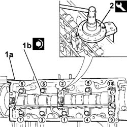
1. Position the cylinder head (1a) and tighten the fixing bolts (1b) to a pre-torque of 2 daNm and then to torque following the order and the figures given.
| Fastening | Component | Ø | Value (daNm) | |
|---|---|---|---|---|
| 1b | Bolt | CYLINDER HEAD | M9 x 1.25 | 3 + 90° + 90° |
2. Always following the same tightening order, complete the angular tightening of the bolts using a suitable tool.
| Description | Code | |
|---|---|---|
| 2 | Torque wrench | 1.860.942.000 |
Op. 1032B10 TOOTHED TIMING BELT - R + R FOR TIMING ADJUSTMENT OR REPLACEMENT
Op. 7055A42 FRONT GRILLE - R+R
Op. 1032D12 TIMING SYSTEM PROTECTIVE COVER(S) - R + R
Op. 1092A10 CRANKSHAFT SERVICES PULLEY - R.R.
Op. 1092B60 ALTERNATOR DRIVE BELT - R + R
Op. 1092B64 ALTERNATOR DRIVE BELT - ADJUST TENSION
Op. 4450B04 RIGHT FRONT WHEEL R R
Fit the new gasket.
Position the tappet cover and secure it using the fixing bolts.
| Fastening | Component | Ø | Value (daNm) | |
|---|---|---|---|---|
| Bolt | CAM COVER | M6 X 1 | 1 |
Fit the oil filler plug.
Fit the exhaust manifold in place and tighten the fixing nut to the torque indicated.
| Fastening | Component | Ø | Value (daNm) | |
|---|---|---|---|---|
| Nut | EXHAUST MANIFOLD/S | M8 X 1.25 | 2.5 |
Op. 1072C44 EXHAUST MANIFOLD HEAT SHIELD ON BULKHEAD - R+R
Tighten the bolt fixing the exhaust manifold retaining bracket to torque.
| Fastening | Component | Ø | Value (daNm) | |
|---|---|---|---|---|
| Bolt | EXHAUST MANIFOLD/S | M8 | (Fastening bracket) 2.5 |
Fit the intake manifold in place complete with throttle casing and single fuel manifold pipe and tighten the fixing nuts to the torque indicated.
| Fastening | Component | Ø | Value (daNm) | |
|---|---|---|---|---|
| Nut | INLET MANIFOLD | M8 X 1.25 | 2.7 |
Refit the electrical wiring duct in the slots in the tappet cover.
Connect the electrical connections for the injectors.
| Description | Connector | |
|---|---|---|
| Injector | N70A |
| Description | Connector | |
|---|---|---|
| Injector | N70B |
| Description | Connector | |
|---|---|---|
| Injector | N70C |
| Description | Connector | |
|---|---|---|
| Injector | N70D |
Connect the electrical connection for the engine idle actuator.
| Description | Connector | |
|---|---|---|
| Idle actuator | N74 |
Connect the electrical connection for the throttle position sensor.
| Description | Connector | |
|---|---|---|
| Throttle position sensor | K56 |
Connect the electrical connection for the fuel vapour recovery solenoid valve.
| Description | Connector | |
|---|---|---|
| Fuel vapour recovery solenoid valve | L10 |
Connect the electrical connection for the built-in air temperature sensor.
| Description | Connector | |
|---|---|---|
| Integrated air temperature sensor | K43 |
Connect the rapid connector for the fuel vapour recovery pipe.
Connect the fuel supply pipe rapid connector.
Connect the single-acting valve pipe and renew the retaining band.
Op. 1080D22 OIL VAPOUR PIPE FROM CAM COVER TO INTAKE R R
Op. 5510C30 ENGINE TIMING SENSOR - R+R
Op. 1056B50 COOLANT TEMPERATURE SENSOR - R + R
Position the accelerator pedal control cable and fit the end on the throttle valve control.
Fit the coolant hose on the thermostat and renew the fastening band.
Fit the ignition coil assembly and tighten the fixing nuts and bolts.
Connect the electrical connections for the ignition coils and the electrical connections for the spark plugs.
| Description | Connector | |
|---|---|---|
| Ignition coil | A30A |
| Description | Connector | |
|---|---|---|
| Ignition coil | A30B |
Op. 5530B52 BATTERY DRIP TRAY/SUPPORT - R.R.
Op. 5530B56 BATTERY DRIP TRAY COVER - R.R.
Op. 7055B54 UNDER-ENGINE GUARD - R R
Op. 1048A10 AIR CLEANER FILTERING ELEMENT - REPLACE
Parts & tools for this job Staging For 2003 Fiat Panda
- PARTEngine gasket setSearch: Fiat Panda 2003 engine gasket set
- TOOLTorque wrenchSearch: 3/8 inch torque wrench
- TOOLFeeler gauge setSearch: feeler gauge set
Links open Amazon search results in a new tab. As an Amazon Associate I earn from qualifying purchases.