
Diesel injection wiring harness - r r
- Make
- Fiat
- Model
- Doblò Factory Service Manual
- Year
- 2000–2010
- Section
- Diesel fuel injection › Diesel injection wiring harness - r r
Diesel injection wiring harness - r r
Removing
Position the car on the ramp.
Ensure that the ignition key is in the OFF position, then disconnect the negative battery terminal.
| Name | Connector | |
|---|---|---|
| Battery | A1 |
Carry out - 5530B10 battery - r+r.
Carry out - 5530B52 Battery DRIP TRAY/SUPPORT - R.R..
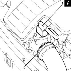
1. Disconnect the electrical connection from the air flow meter.
| Name | Connector | |
|---|---|---|
| 1 | Air flow meter | K41 |
2. Loosen the band and disconnect the the turbocharger air inlet sleeve from the rigid pipe, air flow meter side.
Removing
Position the vehicle on the ramp.
Proceed with the removal - 5530B10 battery - r+r.
Proceed with the removal - 5530B52 Battery DRIP TRAY/SUPPORT - R.R..
Proceed with the removal - 7210E22 R.R. WINDSCREEN BASE TRIM.
Proceed with the removal - 5520C20 Heater plugs CONTROL UNIT - R.R..
Proceed with the removal - 1044B10 fuel filter assembly - r + r or replace.
Proceed with the removal - 1060G50 Electro-pneumatically controlled THROTTLE CASING - R.R..
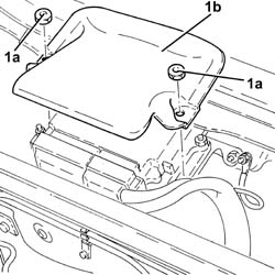
1. Undo the nuts (1a) and remove the protection (1b).
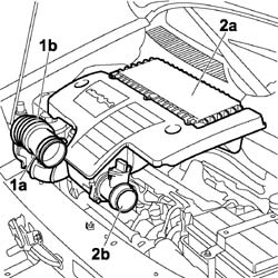
1. Loosen the band (1a) and disconnect the flexible hose (1b) from the air intake.
2. Remove the air filter (2a) complete with air flow meter (2b) by releasing from the underlying pins and then from the rear fastening.
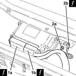
1. Disconnect the electrical connections (1a) and (1b) from the diesel electronic injection system control unit.
| Name | Connector | |
|---|---|---|
| 1a | Engine management ECU | M10A |
| Name | Connector | |
|---|---|---|
| 1b | Engine management ECU | M10B |
2. Undo nut (2a) and disconnect earth lead (2b).
| Name | Connector | |
|---|---|---|
| 2b | Earth on engine | C60 |
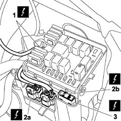
Remove the fastening clips and remove the cover from the engine compartment junction box.
1. Undo the nut and disconnect the positive supply lead in the engine compartment junction box.
| Name | Connector | |
|---|---|---|
| 1 | Engine compartment junction unit | B1A |
2. Using a screwdriver, remove the safety pin and disconnect the electrical connections (2a) and (2b) from the engine compartment junction box.
| Name | Connector | |
|---|---|---|
| 2a | Front/engine coupling | D4A |
| Name | Connector | |
|---|---|---|
| 2b | Front/engine coupling | D4B |
3. Release the retaining clip and remove the spark plugs fuse block (MAXI FUSE) from the engine compartment junction box.
| Name | Connector | |
|---|---|---|
| 3 | Spark plugs (MAXI FUSE) fuse | B37 |
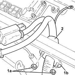
1. Undo the nuts (1a) securing cable duct (1b).
2. Withdraw the wiring complete with electrical connections from the engine bay bulkhead.
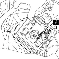
1. Rotate the engine compartment junction unit on its hinges.
2. Disconnect the electrical connection from the engine compartment junction unit.
| Name | Connector | |
|---|---|---|
| 2 | Engine compartment junction unit | B1F |
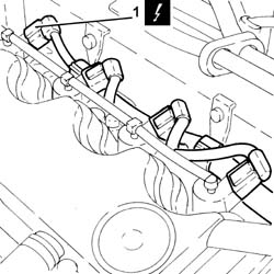
1. Disconnect the electrical connections from the injectors.
| Name | Connector | |
|---|---|---|
| 1 | Injector | N70 |
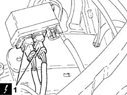
1. Disconnect the electrical connections from the pre-heating control unit.
| Name | Connector | |
|---|---|---|
| 1 | Heater plugs controlunit | M15 |
Proceed with the removal - 1060F50 fuel return manifold - r r.
Proceed with the removal - 1080C24 e.g.r. system solenoid - r + r.
Proceed with the removal - 1060G70 vacum tank for controlling engine air intake r r.
1. Disconnect the electrical connection from the excess pressure sensor.
| Name | Connector | |
|---|---|---|
| 1 | Turbocharging sensor | K82 |
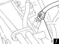
1. Disconnect the electrical connection joining the engine/radiator prewiring cables.
| Name | Connector | |
|---|---|---|
| 1 | Engine cables/radiator cable coupling | D28 |
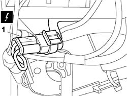
1. Disconnect the electrical connection from the air flow meter.
| Name | Connector | |
|---|---|---|
| 1 | Air flow meter | K41 |
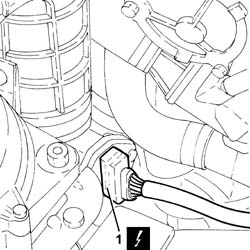
1. Disconnect the electrical connection from the fuel pressure sensor.
| Name | Connector | |
|---|---|---|
| 1 | Fuel pressure sensor | K83 |
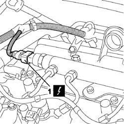
1. Disconnect the electrical connection from the engine coolant temperature sensor.
| Name | Connector | |
|---|---|---|
| 1 | Data not available yet |
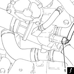
1. Disconnect the electrical connection from the intake air pressure sensor.
| Name | Connector | |
|---|---|---|
| 1 | Turbocharging sensor | K82 |
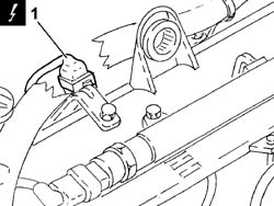
1. Disconnect the electrical connection from the turbocharger vane actuator solenoid.
| Name | Connector | |
|---|---|---|
| 1 | Data not available yet |
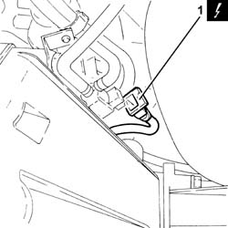
1. Disconnect the electrical connection from the engine coolant temperature sensor.
| Name | Connector | |
|---|---|---|
| 1 | Data not available yet |
2. Disconnect the electrical connection for the rpm sensor.
| Name | Connector | |
|---|---|---|
| 2 | RPM sensor | K46 |
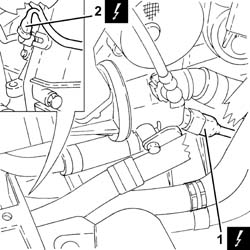
1. Disconnect the electrical connection from the fuel pressure sensor.
| Name | Connector | |
|---|---|---|
| 1 | Fuel pressure sensor | K83 |
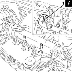
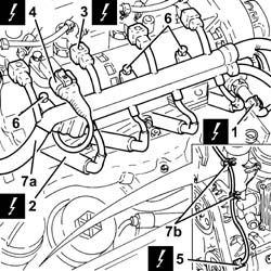
1. Disconnect the electrical connection from the engine oil pressure warning light switch.
| Name | Connector | |
|---|---|---|
| 1 | Insufficient engine oil pressure (switch) sensor | K30 |
2. Disconnect the electrical connections from the heater plugs.
| Name | Connector | |
|---|---|---|
| 2 | Heater plugs | A40 |
3. Disconnect the electrical connections from the injectors.
| Name | Connector | |
|---|---|---|
| 3 | Injector | N70 |
4. Disconnect the electrical connection from the cam angle sensor.
| Name | Connector | |
|---|---|---|
| 4 | Timing sensor | K47 |
5. Disconnect the electrical connection from the air conditioning compressor engagement electromagnet.
| Name | Connector | |
|---|---|---|
| 5 | Air conditioning compressor "on" electromagnet | L20 |
6. Undo the bolts securing the cable pass to the cylinder head.
7. Release the system cable loom (7a) from the attachments (7b) and move it aside.
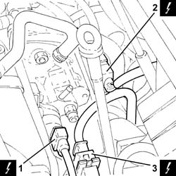
1. Disconnect the electrical connection from the fuel pressure regulator on the fuel pump.
| Name | Connector | |
|---|---|---|
| 1 | Fuel pressure regulator | N77 |
2. Disconnect the electrical connection for the cam angle sensor.
| Name | Connector | |
|---|---|---|
| 2 | Timing sensor | K47 |
3. Disconnect the electrical connection from the solenoid on the vacuum tank.
| Name | Connector | |
|---|---|---|
| 3 | Butterfly casing solenoid valve | L62 |
1. Disconnect the electrical connection from the fuel pressure regulator.
| Name | Connector | |
|---|---|---|
| 1 | Fuel pressure regulator | N77 |
2. Disconnect the electrical connection from the E.G.R. valve.
| Name | Connector | |
|---|---|---|
| 2 | EGR solenoid | L30 |
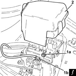
1. Undo the nut (1a) and disconnect supply lead (1b) from the fuse/relay box.
| Name | Connector | |
|---|---|---|
| 1b | Engine compartment junction unit | B1A |
2. Remove the fuse/relay box cover.
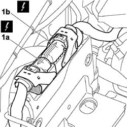
1. Disconnect the electrical connections (1a) and (1b) from the diesel electronic injection system control unit.
| Name | Connector | |
|---|---|---|
| 1a | Engine management ECU | M10A |
| Name | Connector | |
|---|---|---|
| 1b | Engine management ECU | M10B |
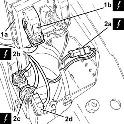
1. Raise the fuse/relay box (1a) and diconnect the electrical connection (1b).
| Name | Connector | |
|---|---|---|
| 1b | Engine compartment junction unit | B1F |
2. Disconnect electrical connections (2a, 2b, 2c) and release fuse (2d).
| Name | Connector | |
|---|---|---|
| 2a | Engine cables/radiator cable coupling | D28 |
| Name | Connector | |
|---|---|---|
| 2b | Front/engine coupling | D4A |
| Name | Connector | |
|---|---|---|
| 2c | Front/engine coupling | D4B |
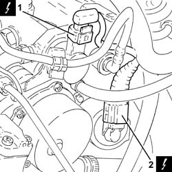
1. Disconnect the electrical connection from the fuel pre-heating device.
| Name | Connector | |
|---|---|---|
| 1 | Fuel temperature sensor | K81 |
2. Disconnect the electrical connection for the water-in-fuel filter sensor.
| Name | Connector | |
|---|---|---|
| 2 | Water in diesel filter sensor | K31 |
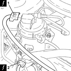
Proceed with the removal - 7055B54 under-engine guard - r r.
1. Disconnect the electrical connection for the air conditioning compressor electromagnet coupling.
| Name | Connector | |
|---|---|---|
| 1 | Air conditioning compressor "on" electromagnet | L20 |
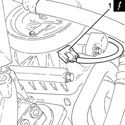
Proceed with removal - 7055B54 under-engine guard - r r.
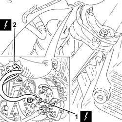
1. Undo the nut (1a) and disconnect the electrical connection (1b) from the alternator.
| Name | Connector | |
|---|---|---|
| 1b | Alternator | A10 |
2. Open the protective cover (2a), undo the nut (2b) and disconnect the electrical connection (2c) from the starter motor.
| Name | Connector | |
|---|---|---|
| 2c | Starter motor | A20 |
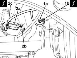
Undo the fastenings and remove the engine oil dipstick pipe.
1. Disconnect the electrical connection for the rpm sensor then remove the bracket.
| Name | Connector | |
|---|---|---|
| 1 | RPM sensor | K46 |
2. Disconnect the electrical connections from the starter motor.
| Name | Connector | |
|---|---|---|
| 2 | Starter motor | A20 |
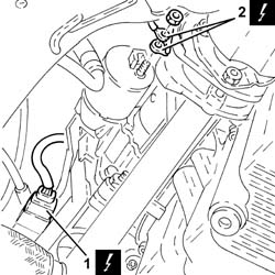
Release the cable loom from the bands securing it to the air chamber and remove it.
1. Disconnect the electrical connections from the alternator.
| Name | Connector | |
|---|---|---|
| 1 | Alternator | A10 |
2. Disconnect the electrical connection from the engine oil pressure warning light switch.
| Name | Connector | |
|---|---|---|
| 2 | Insufficient engine oil pressure (switch) sensor | K30 |
Refitting
Refit in its seating the system cable loom and secure it to the bands on the air chamber.
Connect the electrical connection to the starter motor, secure it with the nut and close the protective cover.
| Name | Connector | |
|---|---|---|
| Starter motor | A20 |
Connect the alternator electrical connection and tighten the fixing nut.
| Name | Connector | |
|---|---|---|
| Alternator | A10 |
Carry out - 7055B54 under-engine guard - r r.
Connect the electrical connection to the water-in-fuel filter presence sensor.
| Name | Connector | |
|---|---|---|
| Water in diesel filter sensor | K31 |
Connect the electrical connection to the fuel pre-heating device.
| Name | Connector | |
|---|---|---|
| Fuel temperature sensor | K81 |
Connect the electrical connections to the diesel electronic injection control unit.
| Name | Connector | |
|---|---|---|
| Engine management ECU | M10A |
| Name | Connector | |
|---|---|---|
| Engine management ECU | M10B |
Connect the electrical connection to the EGR solenoid.
| Name | Connector | |
|---|---|---|
| EGR solenoid | L30 |
Connect the electrical connection to the fuel pressure regulator.
| Name | Connector | |
|---|---|---|
| Fuel pressure regulator | N77 |
Connect the electrical connection to the intake air pressure sensor.
| Name | Connector | |
|---|---|---|
| Turbocharging sensor | K82 |
Connect the electrical connection to the fuel pressure sensor.
| Name | Connector | |
|---|---|---|
| Fuel pressure sensor | K83 |
Refit the wiring loom in its seating and secure it.
Tighten the bolts securing the cable pass to the cylinder head.
Connect the electrical connection to the air conditioner compressor electromagnet.
| Name | Connector | |
|---|---|---|
| Air conditioning compressor "on" electromagnet | L20 |
Connect the electrical connection to the cam angle sensor.
| Name | Connector | |
|---|---|---|
| Timing sensor | K47 |
Connect the electrical connections to the injectors.
| Name | Connector | |
|---|---|---|
| Injector | N70 |
Connect the electrical connections to the heater plugs.
| Name | Connector | |
|---|---|---|
| Heater plugs | A40 |
Connect the electrical connection to the engine oil pressure warning light switch.
| Name | Connector | |
|---|---|---|
| Insufficient engine oil pressure (switch) sensor | K30 |
Connect the electrical connection for the rpm sensor.
| Name | Connector | |
|---|---|---|
| RPM sensor | K46 |
Disconnect the electrical connection from the engine coolant temperature sensor.
| Name | Connector | |
|---|---|---|
| Data not available yet |
Connect the electrical connection for the engine/radiator prewiring cables junction.
| Name | Connector | |
|---|---|---|
| Engine cables/radiator cable coupling | D28 |
Connect the electrical connections to the pre-heating control unit.
| Name | Connector | |
|---|---|---|
| Heater plugs controlunit | M15 |
Connect the electrical connection to the engine compartment junction box.
| Name | Connector | |
|---|---|---|
| Engine compartment junction unit | B1F |
Refit the engine compartment junction box in its seating, rotating it on its hinges.
Connect the electrical connections to the engine compartment junction box.
| Name | Connector | |
|---|---|---|
| Front/engine coupling | D4A |
| Name | Connector | |
|---|---|---|
| Front/engine coupling | D4B |
| Name | Connector | |
|---|---|---|
| Spark plugs (MAXI FUSE) fuse | B37 |
Connect the positive supply lead to the engine compartment junction unit and fasten it using the nut.
| Name | Connector | |
|---|---|---|
| Engine compartment junction unit | B1A |
Refit the engine compartment junction box cover in its seating.
Position in its seating the air filter complete with air flow meter, engaging it in the rear attachment and then in the underlying pins.
Connect the flexible hose to the air intake on the crossmember and tighten the fixing band.
Connect the air intake hose to the turbocharger, air flow meter side, and tighten the fixing band.
Connect the electrical connection to the air flow meter.
| Name | Connector | |
|---|---|---|
| Air flow meter | K41 |
Carry out - 5530B52 Battery DRIP TRAY/SUPPORT - R.R..
Carry out - 5530B10 battery - r+r.
Connect the battery negative terminal.
| Name | Connector | |
|---|---|---|
| Battery | A1 |
Remove the car from the ramps.
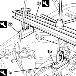
Proceed with the removal - 1008A46 cam shaft left rigid mount - r r.
1. Fit tool (1a) to the pressure pump mount and secure with nuts (1b).
| Name | Country | |
|---|---|---|
| 1a | Mount | 1.860.625.000 |
2. Fit tool (2a), complete with support blocks (2b) and connect to the bracket fitted previously using link (2c).
| Name | Country | |
|---|---|---|
| 2a | Crossmember | 1.870.595.000 |
| Name | Country | |
|---|---|---|
| 2b | Support mountings | 1.870.650.000 |
Remove the hydraulic lift from beneath the power unit.
The above operations must be carried out in order to remove the air conditioner electrical connection.
Remove the system cable loom.
Refitting
Fit the system wiring harness in its seat.
Position the hydraulic lift beneath the power unit.
Remove the safety tools used for supporting the power unit.
| Name | Country | |
|---|---|---|
| Crossmember | 1.870.595.000 |
| Name | Country | |
|---|---|---|
| Support mountings | 1.870.650.000 |
| Name | Country | |
|---|---|---|
| Mount | 1.860.625.000 |
Proceed with the refitting - 1008A46 cam shaft left rigid mount - r r.
Connect the electrical connection to the engine oil pressure warning light switch.
Connect the electrical connections to the alternator.
Connect the electrical connections to the starter motor.
Refit the bracket, then connect the rpm sensor electrical connection.
Place the engine oil dipstick tube assembly back in its housing and secure.
Connect the electrical connection to the air conditioning compressor electromagnet coupling.
Proceed with the refitting - 7055B54 under-engine guard - r r.
Connect the electrical connections and refit together with the fuse.
Connect the electrical connection to the fuse/relay box and place it back in its housing.
Refit the fuse/relay box cover in its seat.
Connect the fuse/relay box supply lead and tighten the nut.
Connect the electrical connection to the solenoid on the vacuum tank.
Connect the electrical connection for the cam angle sensor.
Connect the electrical connection to the pressure regulator on the pressure pump.
Connect the electrical connection to the fuel pressure sensor.
Connect the electrical connection to the turbocharger vane actuator solenoid.
Connect the electrical connection to the engine coolant temperature sensor.
Connect the electrical connection to the air flow meter.
Connect the electrical connection to the excess pressure sensor.
Proceed with the refitting - 1060G70 vacum tank for controlling engine air intake r r.
Proceed with the refitting - 1080C24 e.g.r. system solenoid - r + r.
Proceed with the refitting - 1060F50 fuel return manifold - r r.
Connect the electrical connections to the injectors.
Fit the wiring with electrical connections for the diesel electronic injection system through the tunnel in the engine bulkhead.
Tighten the cable duct nuts.
Connect the earth lead and fix it using the nut.
Connect the electrical connections to the diesel electronic injection control unit.
Place the protection back in its housing and fix it using the nuts.
Proceed with the refitting - 1060G50 Electro-pneumatically controlled THROTTLE CASING - R.R..
Proceed with the refitting - 1044B10 fuel filter assembly - r + r or replace.
Proceed with the refitting - 5520C20 Heater plugs CONTROL UNIT - R.R..
Proceed with the refitting - 7210E22 R.R. WINDSCREEN BASE TRIM.
Proceed with the refitting - 5530B52 Battery DRIP TRAY/SUPPORT - R.R..
Proceed with the refitting - 5530B10 battery - r+r.
Remove the car from the ramp.
Parts & tools for this job Staging For 2000 Fiat Doblò
- PARTGlow plugsSearch: Fiat Doblò 2000 glow plugs
- TOOLGlow plug socketSearch: glow plug socket
- TOOLDiesel compression testerSearch: diesel compression tester
Links open Amazon search results in a new tab. As an Amazon Associate I earn from qualifying purchases.