
Power unit intermediate mount flexible block - replace
- Make
- Alfa Romeo
- Model
- GT Factory Service Manual
- Year
- 2003–2010
- Section
- Power unit supports › Power unit intermediate mount flexible block - replace
POWER UNIT INTERMEDIATE MOUNT FLEXIBLE BLOCK - REPLACE
Removing
Position the vehicle on a lift.
Proceed with the removal
Op. 7055B54 UNDER-ENGINE GUARD - R R.
Proceed with the removal
Op. 1076B18 RIGID SECTION OF EXHAUST PIPE BETWEEN CATALYTIC CONVERTER AND SILENCER - R + R.
Proceed with the removal
Op. 1076A32 EXHAUST RIGID MOUNT - R R.
Position a hydraulic jack beneath the engine.
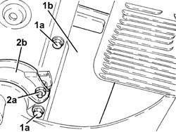
1. Undo the bolts (1a) and remove the heat shield (1b).
2. Undo the nuts (2a) and remove the flexible mounting heat shield (2b).
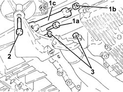
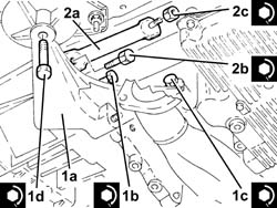
1. Undo the bolt (1a) and the nut (1b) and remove the reinforcement rod (1c).
2. Unscrew the bolt securing the power unit rigid rear support to the flexible mounting.
3. Loosen the bolts fixing the rigid rear support to the gearbox and to the engine oil sump, then rotate it as much as necessary to move it away from the flexible mounting.
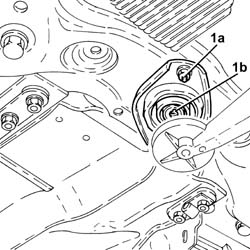
1. Undo the bolts (1a) and remove the flexible mounting for the power unit rear support (1b).
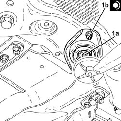
Refitting
1. Place the power unit rear support flexible mounting (1a) in its housing and secure it to the crossmember tightening the bolts (1b) to the recommended torque.
| Fastening | Component | Ø | Value (daNm) | |
|---|---|---|---|---|
| 1b | Bolt | INTERM RUBBER MOUNT | M8 | (Front suspension crossmember side) 3.2 - 3.9 |
1. Place the power unit rigid rear support (1a) in its housing and secure it tightening the bolts (1b, (1c) and (1d) to the recommended torque.
| Fastening | Component | Ø | Value (daNm) | |
|---|---|---|---|---|
| 1b | Bolt | RIGID REAR SUPPORT POWER UNIT | M12 | (Gearbox side) 7.2 - 8.8 |
| Fastening | Component | Ø | Value (daNm) | |
|---|---|---|---|---|
| 1c | Bolt | RIGID REAR SUPPORT POWER UNIT | M12 | (Engine crankcase side) 6.8 - 8.3 |
| Fastening | Component | Ø | Value (daNm) | |
|---|---|---|---|---|
| 1d |
2. Place the reinforcement rod (2a) in its housing and fasten it tightening the bolt (2b) and the nut (2c) to the recommended torque.
| Fastening | Component | Ø | Value (daNm) | |
|---|---|---|---|---|
| 2b | Bolt | REINFORCEMENT ROD FOR POWER UNIT RIGID REAR SUPPORT | M12 |
| Fastening | Component | Ø | Value (daNm) | |
|---|---|---|---|---|
| 2c |
Place the heat shield for the flexible mounting back in its housing and fasten it using the nuts.
Place the heat shield back in its housing and secure it using the bolts.
Remove the hydraulic jack from beneath the engine.
Proceed with the refitting
Op. 1076A32 EXHAUST RIGID MOUNT - R R.
Proceed with the refitting
Op. 1076B18 RIGID SECTION OF EXHAUST PIPE BETWEEN CATALYTIC CONVERTER AND SILENCER - R + R.
Proceed with the refitting
Op. 7055B54 UNDER-ENGINE GUARD - R R.
Remove the vehicle from the lift.
Removing
Position the vehicle on a lift.
Proceed with the removal
Op. 7055B54 UNDER-ENGINE GUARD - R R.
Proceed with the removal
Op. 1076B82 LEFT EXHASUST PIPE BETWEEN CATALYTIC PRECONVERTER AND CONVERTER R R.
Proceed with the removal
Op. 1008A44 REAR RIGID MOUNT - R R.
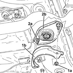
1. Undo the nuts (1a) and remove the heat shield (1b).
2. Undo the bolts (2a) and remove the flexible mounting for the power unit rear support (2b).
Refitting
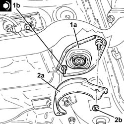
1. Place the power unit rear support flexible mounting (1a) in its housing and secure it to the crossmember tightening the bolts (1b) to the recommended torque.
| Fastening | Component | Ø | Value (daNm) | |
|---|---|---|---|---|
| 1b | Bolt | INTERM RUBBER MOUNT | M8 | (Front suspension crossmember side) 3.3 - 3.9 |
2. Place the heat shield (2a) in its housing and secure it using the nuts.
Proceed with the refitting
Op. 1008A44 REAR RIGID MOUNT - R R.
Proceed with the refitting
Op. 1076B82 LEFT EXHASUST PIPE BETWEEN CATALYTIC PRECONVERTER AND CONVERTER R R.
Proceed with the refitting
Op. 7055B54 UNDER-ENGINE GUARD - R R.
Remove the vehicle from the lift.
Removing
Position the vehicle on a lift.
Proceed with the removal
Op. 7055B54 UNDER-ENGINE GUARD - R R.
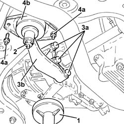
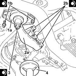
1. Position a hydraulic jack beneath the gearbox.
2. Undo the nut securing the power unit rigid rear support to the flexible mounting.
3. Undo the bolts (3a) and remove the power unit rigid rear support (3b).
4. Undo the bolts (4a) and remove the flexible mounting for the power unit rear support (4b).
Refitting
1. Place the power unit rear support flexible mounting (1a) in its housing and secure it to the crossmember tightening the bolts (1b) to the recommended torque.
| Fastening | Component | Ø | Value (daNm) | |
|---|---|---|---|---|
| 1b | Bolt | INTERM RUBBER MOUNT | M8 | (Front suspension crossmember side) 3.2 - 3.9 |
2. Place the power unit rigid rear support (2a) in its housing and secure it tightening the bolts (2b) to the recommended torque.
| Fastening | Component | Ø | Value (daNm) | |
|---|---|---|---|---|
| 2b | Bolt | RIGID REAR SUPPORT POWER UNIT | M10 | (Manual gearbox/differential side) 4.5 - 5.5 |
3. Tighten the nut securing the power unit side rigid rear support to the flexible mounting to the recommended torque.
| Fastening | Component | Ø | Value (daNm) | |
|---|---|---|---|---|
| 3 |
4. Remove the hydraulic jack from beneath the gearbox
Proceed with the refitting
Op. 7055B54 UNDER-ENGINE GUARD - R R.
Remove the vehicle from the lift.
Removing
Position the vehicle on a lift.
Make sure that the ignition key is in the OFF position, then disconnect the negative battery terminal.
| Description | Connector | |
|---|---|---|
| Battery | Vedere A1B BATTERIA ( CABLAGGI ) |
Proceed with the removal
Op. 1072C44 EXHAUST MANIFOLD HEAT SHIELD ON BULKHEAD - R+R.
Proceed with the removal
Op. 1080B40 CATALYTIC PRE-CONVERTER - R R.
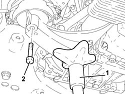
1. Position a hydraulic jack under the power unit rigid rear support.
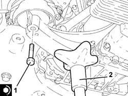
2. Unscrew the bolt securing the power unit rigid rear support to the flexible mounting.
Lower the power unit rigid rear support as necessary using the hydraulic jack.
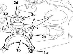
1. Undo the nuts (1a) and remove the heat shield (1b).
2. Undo the bolts (2a) and remove the flexible mounting for the power unit rear support (2b), complete with shim (2c) and nut (2d).
Refitting
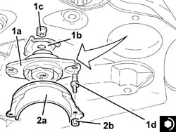
1. Place a new flexible mounting for the power unit rear support (1a) in its housing complete with shim (1b) and nut (1c), then fasten it tightening the bolts (1d) to the recommended torque.
| Fastening | Component | Ø | Value (daNm) | |
|---|---|---|---|---|
| 1d | Bolt | INTERM RUBBER MOUNT | M8 | (Front suspension crossmember side) 3.2 - 3.9 |
2. Place the heat shield (2a) back in its housing and fasten it using the nuts (2b).
Place the power unit rigid rear support in its housing using the hydraulic jack.
1. Tighten the bolt securing the power unit side rigid rear support to the flexible mounting to the recommended torque.
| Fastening | Component | Ø | Value (daNm) | |
|---|---|---|---|---|
| 1 | Bolt | RIGID REAR SUPPORT POWER UNIT | M12 | (Flexible mounting side) 7.5 - 9.2 |
2. Remove the hydraulic jack positioned under the power unit rigid rear support.
Proceed with the refitting
Op. 1080B40 CATALYTIC PRE-CONVERTER - R R.
Proceed with the refitting
Op. 1072C44 EXHAUST MANIFOLD HEAT SHIELD ON BULKHEAD - R+R.
Connect the negative battery terminal (-).
Remove the vehicle from the lift.
Parts & tools for this job Staging For 2003 Alfa Romeo GT
- PARTEngine gasket setSearch: Alfa Romeo GT 2003 engine gasket set
- TOOLTorque wrenchSearch: 3/8 inch torque wrench
- TOOLFeeler gauge setSearch: feeler gauge set
Links open Amazon search results in a new tab. As an Amazon Associate I earn from qualifying purchases.