
Brake fluid reservoir - r + r and wash inside
- Make
- Alfa Romeo
- Model
- GT Factory Service Manual
- Year
- 2003–2010
- Section
- Hydraulic braking system › Brake fluid reservoir - r + r and wash inside
BRAKE FLUID RESERVOIR - R + R AND WASH INSIDE
Removing
Position the vehicle on a lift.
Proceed with the removal
Op. 4450B02 LEFT FRONT WHEEL R R.
Remove the protective cap from the bleed valve on the brake caliper.
Connect the recovery device (pipe and reservoir) to the brake caliper bleed valve.
Loosen the bleed valve on the brake caliper.
Operate the brake pedal until the brake/clutch reservoir is drained.
Proceed with the removal
Op. 1016A40 IGNITION COIL COVER ON CYLINDER HEAD- R+R.
Proceed with the removal
Op. 1048A59 PIPE from flow meter to throttle casing hose - R.R..
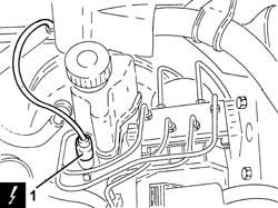
1. Disconnect the electrical connection from the brake fluid minimum level warning light switch.
| Description | Connector | |
|---|---|---|
| 1 | Brake fluid level sensor (switch) | See K25 BRAKE FLUID LEVEL SENSOR (SWITCH) ( FRONT ) |
Proceed with the removal
Op. 3340B52 PUMP/CENTRAL OBS PIPE - R R
(Both).
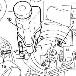
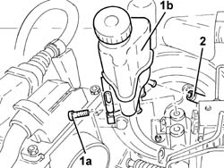
1. Undo the bolt (1a) and lift up the brake fluid reservoir (1b) as much as necessary releasing it from the master cylinder.
2. Disconnect the flexible pipe from the reservoir to the clutch master cylinder, reservoir side.
Remove the brake fluid reservoir.
Refitting
Wash the inside of the brake fluid reservoir.
Connect the flexible pipe from the reservoir to the clutch master cylinder, reservoir side.
Place the brake fluid reservoir in position connecting it to the master cylinder, then secure it using the bolt.
Proceed with the refitting
Op. 3340B52 PUMP/CENTRAL OBS PIPE - R R
(Both).
Connect the electrical connection to the brake-clutch fluid minimum level warning light switch.
Proceed with the refitting
Op. 1048A59 PIPE from flow meter to throttle casing hose - R.R..
Proceed with the refitting
Op. 1016A40 IGNITION COIL COVER ON CYLINDER HEAD- R+R.
Proceed with the refitting
Op. 0010T64 BRAKE AND OR CLUTCH FLUID CHECK LEVEL AND TOP UP AS NECESSARY.
Proceed with the refitting
Op. 0010T65 HYDRAULIC BRAKE SYSTEM BLEED AIR.
Proceed with the refitting
Op. 4450B02 LEFT FRONT WHEEL R R.
Remove the vehicle from the lift.
Removing
Position the vehicle on a lift.
Make sure that the ignition key is in the OFF position, then disconnect the battery terminal (-).
| Description | Connector | |
|---|---|---|
| Battery | See A1B BATTERY ( BATTERY NEGATIVE ) |
Proceed with the removal
Op. 4450B02 LEFT FRONT WHEEL R R.
Remove the protective cap from the bleed valve on the brake caliper.
Connect the recovery device (pipe and reservoir) to the brake caliper bleed valve.
Operate the brake pedal until the brake/clutch reservoir is drained.
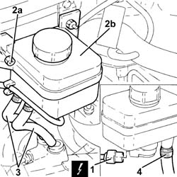
1. Disconnect the electrical connection from the brake fluid minimum level warning light switch.
| Description | Connector | |
|---|---|---|
| 1 | Brake fluid level sensor (switch) | See K25 BRAKE FLUID LEVEL SENSOR (SWITCH) ( FRONT ) |
2. Undo the nuts (2a) and lift up the brake fluid reservoir (2b) as necessary.
3. Disconnect the pipes from the brake fluid reservoir to the master cylinder, reservoir side.
4. Disconnect the flexible pipe from the reservoir to the clutch master cylinder, reservoir side.
Remove the brake fluid reservoir.
Refitting
Wash the inside of the brake fluid reservoir.
Connect the flexible pipe from the reservoir to the clutch master cylinder, reservoir side.
Connect the pipes from the brake fluid reservoir to the master cylinder, reservoir side.
Place the brake fluid reservoir back in its housing and secure it using the nuts.
Connect the electrical connection to the brake-clutch fluid minimum level warning light switch.
Top up the brake-clutch fluid level
Op. 0010T64 BRAKE AND OR CLUTCH FLUID CHECK LEVEL AND TOP UP AS NECESSARY.
Bleed the air from the hydraulic braking system
Op. 3330A14 FRONT OR REAR HYDRAULIC BRAKE SYSTEM - BLEED.
Proceed with the refitting
Op. 4450B02 LEFT FRONT WHEEL R R.
Connect the negative battery terminal (-).
Remove the vehicle from the lift.
Removing
Proceed with the removal
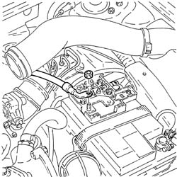
During the removal of the battery take care to also disconnect the starter motor supply lead, shown in the diagram, from the maxi fuse box.
Remove the brake-clutch fluid reservoir cap and draw off the fluid using a suitable syringe, then retighten the cap.
1. Disconnect the electrical connection from the brake fluid minimum level warning light switch.
| Description | Connector | |
|---|---|---|
| 1 | Brake fluid level sensor (switch) | See K25 BRAKE FLUID LEVEL SENSOR (SWITCH) ( FRONT ) |
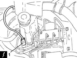
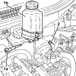
1. Undo the bolt (1a) and lift up the brake fluid reservoir (1b) as much as necessary releasing it from the master cylinder.
2. Disconnect the flexible pipe from the reservoir to the clutch master cylinder, reservoir side.
Remove the brake fluid reservoir.
Refitting
Wash the inside of the brake fluid reservoir.
Connect the flexible pipe from the reservoir to the clutch master cylinder, reservoir side.
Place the brake fluid reservoir in position connecting it to the master cylinder, then secure it using the bolt.
Connect the electrical connection to the brake-clutch fluid minimum level warning light switch.
Bleed the air from the hydraulic braking system
Op. 0010T65 HYDRAULIC BRAKE SYSTEM BLEED AIR.
Proceed with the refitting
Removing
Position the vehicle on a lift.
Proceed with the removal
Op. 4450B02 LEFT FRONT WHEEL R R.
Remove the protective cap from the bleed valve on the brake caliper.
Connect the recovery device (pipe and reservoir) to the brake caliper bleed valve.
Operate the brake pedal until the brake/clutch reservoir is drained.
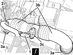
1. Disconnect the electrical connection from the air flow meter.
| Description | Connector | |
|---|---|---|
| 1 | Air flow meter | K41 |
2. Disconnect the oil vapour recirculation pipe from the air intake hose.
3. Loosen the bands (3a) and remove the hose from the filter to the throttle casing with the integrated D.V.L. (3b) complete with air flow meter (3c).
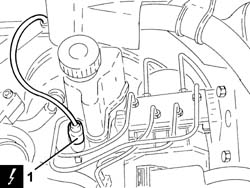
1. Disconnect the electrical connection from the brake fluid minimum level warning light switch.
| Description | Connector | |
|---|---|---|
| 1 | Brake fluid level sensor (switch) | K25 |
Proceed with the removal
3340B52 TUBAZIONE rigida (una), da cilindro maestro (pompa) a centralina idraulica A.B.S. - S.R.
(Both).
1. Undo the bolt (1a) and lift up the brake fluid reservoir (1b) as much as necessary releasing it from the master cylinder.
2. Disconnect the flexible pipe from the reservoir to the clutch master cylinder, reservoir side.
Remove the brake fluid reservoir.
Refitting
Wash the inside of the brake fluid reservoir.
Connect the flexible pipe from the reservoir to the clutch master cylinder, reservoir side.
Place the brake fluid reservoir in position connecting it to the master cylinder, then secure it using the bolt.
Proceed with the refitting
3340B52 TUBAZIONE rigida (una), da cilindro maestro (pompa) a centralina idraulica A.B.S. - S.R.
(Both).
Connect the electrical connection to the brake-clutch fluid minimum level warning light switch.
Place the hose from the filter to the throttle casing with the integrated D.V.L. complete with air flow meter back in its housing and secure it using the bands.
Connect the oil vapour recirculation pipe to the air intake hose.
Connect the electrical connection to the air flow meter.
Bleed the air from the hydraulic braking system
Op. 0010T65 HYDRAULIC BRAKE SYSTEM BLEED AIR.
Proceed with the refitting
Op. 4450B02 LEFT FRONT WHEEL R R.
Remove the vehicle from the lift.
Removing
Open the bonnet.
1. Undo the cover for the brake fluid reservoir.
2. Draw off the brake fluid from the reservoir using a suitable syringe.
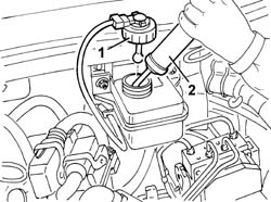
1. Disconnect the electrical connection from the brake fluid level sensor.
| Description | Connector | |
|---|---|---|
| 1 | Brake fluid level sensor (switch) | See K25 BRAKE FLUID LEVEL SENSOR (SWITCH) |
2. Tighten the reservoir cover.
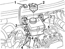
3. Undo the bolts fixing the brake fluid reservoir.
4. Move the brake fluid reservoir slightly and disconnect the pipes.
5. Keep the brake fluid reservoir.
Refitting
Wash the inside of the brake fluid reservoir.
Place the brake fluid reservoir in position and connect the pipes.
Fasten the brake fluid reservoir to the engine compartment bulkhead using the bolts.
| Fastening | Component | Ø | Value (daNm) | |
|---|---|---|---|---|
| Bolt | BRAKE FLUID RESERVOIR | M6 | 0.80 |
Connect the electrical connection to the brake fluid level sensor.
Parts & tools for this job Staging For 2003 Alfa Romeo GT
- TOOLBrake bleeder kitSearch: one man brake bleeder kit
- FLUIDBrake fluidSearch: brake fluid
- TOOLBrake line flaring toolSearch: brake line flaring tool
Links open Amazon search results in a new tab. As an Amazon Associate I earn from qualifying purchases.