
Introduction - petrol fuel injection system
- Make
- Alfa Romeo
- Model
- 159 Factory Service Manual
- Year
- 2005–2011
- Section
- Petrol injection system › Introduction - petrol fuel injection system
INTRODUCTION - PETROL FUEL INJECTION SYSTEM
OPERATION OF THE INJECTION-IGNITION SYSTEM
The Bosch Motronic MED7.6.1 system with a motorized throttle belongs the category of systems integrated with:
- ignition,
- phased sequential electronic injection.
The control unit controls the air flow rate at the idling speed set by the electronic throttle.
The control unit controls the ignition time, with the benefit of maintaining smooth engine operation even when environmental and applied load parameters change.
The control unit controls and manages injection so that stoichiometric air/fuel ratio is always within optimum limits.
The main system functions are essentially as follows:
- self-learning;
- system self-adaptation;
- self-diagnosis;
- recognition of the Alfa Romeo CODE (immobilizer);
- cold starting check control;
- control of combustion - Lambda sensors;
- phase transformer control;
- detonation control;
- control of mixture enrichment during acceleration;
- fuel cut-off when accelerator pedal is released;
- fuel vapour recovery;
- control of maximum rpm;
- high pressure fuel pump control;
- connection with the climate control system;
- cylinder position recognition;
- control of optimum injection time for each cylinder;
- adjustment of ignition advance;
- idle speed management (also dependent on battery voltage);
- fan control;
- connection with ABS/ASR control unit;
- connection with the control panel;
- fuel system diagnostics;
- catalytic converter diagnostics;
- misfire detection;
- Lambda sensor diagnostics.
Injection system
The essential conditions to be met by the air-fuel mixture for efficient operation of engines with controlled ignition systems are mainly as follows:
- the metering (air/fuel ratio) must be kept as close as possible to stoichiometric levels to assure maximum catalytic converter conversion capacity (max. efficiency);
- the homogeneity of the mixture, consisting of petrol distributed throughout the air as finely and uniformly as possible.
Information that the control unit processes to control optimum metering is received by electrical signals emitted by:
- air flow meter and air temperature sensor, for the exact quantity of air taken in;
- rpm sensor that generates an alternating single-phase signal whose frequency is an indicator of engine rpm;
- accelerator pedal with built-in potentiometer to recognize the conditions requested by the driver;
- coolant temperature sensor on the thermostat;
- Lambda sensors to measure exhaust gas oxygen content.
Ignition system
The ignition system is the static, inductive discharge type (i.e. without a high tension distributor).
The system has a single coil for each spark plug with an integrated power stage; the advantages of this solution are:
- lower electrical overload;
- guaranteed constant discharge at each spark plug.
At the idle speed only the ignition coils receive a dual pilot signal (two ignitions) and one signal only (single ignition).
The control unit contains a memory map with a set of optimum ignition advance values (for the cylinder in combustion phase) that the engine can adopt according to the required speed and engine load.
The control unit corrects the advance value mainly on the basis of:
- engine coolant temperature;
- intake air temperature;
- detonation.
Information that the control unit processes to operate the single coils is received by electrical signals emitted by:
- air flow meter and air temperature sensor, for the exact quantity of air taken in;
- rpm sensor that generates an alternating single-phase signal whose frequency is an indicator of engine rpm;
- detonation sensor, to recognize the cylinder with detonation and correct the ignition advance;
- throtle potentiometer to recognize minimum, partial and full-gas load conditions;
- timing sensor.
The control unit uses the rpm signal to recognize misfiring that could damage the catalytic converters.
Operation
Diagram showing information entering/leaving the control unit
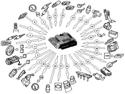
1. Injectors
2. Fuel pump
3. Air conditioning compressor
4. Engine cooling fan
5. Cruise Control system control
6. Lambda sensor downstream of the catalytic converter
7. Air conditioning system gas pressure linear sensor
8. Brake pedal switch
9. Speedometer signal
10. Lambda sensor upstream of the catalytic converter
11. Coolant temperature sensor
12. Timing sensors
13. Detonation sensors
14. Fuel pressure sensor
15. Rpm sensor
16. Accelerator pedal potentiometer
17. Flow meter
18. Battery
19. Clutch pedal switch
20. Motorized throttle body
21. CAN line
22. Alfa CODE
23. Diagnostic socket
24. Fuel vapour recirculation solenoid valve
25. Ignition coils
26. Phase transformer solenoid valves
27. Injection warning light
28. Oil pressure switch
29 - Engine rpm signal
30 - Fuel pressure regulator
System operating logics
Self-learning
The control unit implements the self-learning logic in the following conditions:
- installation of a new injection control unit,
- installation of a new throttle body actuator integrated with D.V.L.
- installation of a new modular intake manifold.
The self-learning values for the integrated throttle body with D.V.L. are preserved with the battery disconnected.
The learning values for the flywheel for recognizing misfiring are, on the other hand, lost.
System self-adjustment
The control unit is equipped with a self-adjustment function that is designed to recognize the changes that take place in the engine due to the processes of bedding in and ageing of both the components and the engine itself in time.
There are two adaptive functions depending on the two intervention plans: minimum and utilization.
Self-diagnosis
The control unit auto-diagnostic system checks that the system is working properly and signals any irregularities by means of an MIL warning light in the instrument panel with a standardized ideogram and colour laid down by European regulations. This warning light indicates engine management faults and also faults detected by EOBD diagnostic strategies.
The MIL warning light operating strategy is as follows:
- with the ignition on, the warning light comes on and remains on until the engine has been started up. The control unit self-diagnostic system checks the signals coming from the sensors comparing them with the permitted limits.
Fault indication during start up:
- the failure of the warning light to go out when the engine has been started indicates that there is an error memorized in the control unit.
Fault indication during operation:
- the warning light comes on in flashing mode to indicate possible catalytic converter damage due to misfiring;
- the warning light comes on in constant mode to indicate the presence of engine management or EOBD diagnostic errors.
RECOVERY
From time to time the control unit defines the type of recovery according to the components that are faulty. The recovery parameters are managed by components that are not faulty.
Cold starting check
In cold starting conditions, the mixture naturally becomes leaner and this gives rise to low fuel evaporation at low temperatures:
- fuel condensation on inner walls of the intake manifold;
- increased lubrication oil viscosity.
The electronic control unit detects this condition and corrects the injection time on the basis of:
- coolant temperature;
- intake air temperature;
- battery voltage;
- engine rpm.
The ignition advance is determined solely on the basis of rpm and coolant temperature.
During the start-up stage, the control unit sends an initial simultaneous injection command to all injectors (full-group injection). Once cylinder phase has been detected, normal phased sequential operation can begin. At idle speed the injection angle is 45° before T.D.C.; at other speeds the injection angle varies between 310° and 370° before T.D.C. to allow the homogeneity of the mixture.
While the engine is warming up, the control unit operates throttle body built into the DVL to modulate the amount of air required to ensure engine revs are high enough to keep the engine running.
The rotation speed is decreased as the temperature increases until the rated level is reached with the engine warm.
Combustion - lambda sensor check
In EOBD systems, the Lambda sensors are all the same type and are located upstream and downstream of the catalytic converter.
The upstream sensors monitor concentration and are known as the 1st loop (closed loop of upstream sensors). During idling the information from the upstream Lambda sensors is not used for correcting the mixture strength.
The sensors downstream of the catalytic converter are used to for converter diagnostics and to fine-tune 1st loop control parameters.
The second loop is therefore adaptive to make up for production discrepancies and slight drift that upstream sensor responses could experience due to ageing and contamination.
This control is known as 2nd loop control (downstream sensors closed loop).
Phase transformer control
In order to ensure the optimum quantity of air introduced by the engine, the control unit controls:
- the intake timing in two angular positions.
The control unit sets the open stage at the maximum torque speed:
- cam advance of 25° engine.
The control unit sets the closed stage at the maximum power speed:
- cam in normal position.
The control unit sets the closed stage at the idle speed:
- cam in normal position.
In the other engine operating conditions, the control unit selects the most suitable configuration for optimum performance, consumption and emissions.
Detonation control
The control unit may delay ignition selectively for a particular cylinder on the basis of a combination of parameters received from knock and timing sensors and:
- reduce ignition advance in 3° steps to a maximum of 9°;
- update the threshold to take into account underlying noise levels and engine ageing.
During acceleration, the control unit uses a higher threshold due to the higher engine noise.
When the knock disappears, the control unit increases ignition advance in 0.75° steps until recovery is complete.
The control unit with a self-adaptive function:
- stores advance reductions that are repeated continuously;
- adjusts mapping to the various different engine service conditions.
RECOVERY
If the timing sensor or knock sensor or injection control unit should fail, a variable ignition delay is implemented on the basis of rpm and engine temperature. Maximum ignition delay is always less than 9° engine.
Control of enrichment during acceleration
In cases of high acceleration demand, the control unit modifies injection time and throttle position.
RECOVERY
The control unit replaces the signal from the faulty air flow meter with a signal from the potentiometer built into the throttle body actuator integral with the DVL.
Fuel cut-off when the accelerator pedal is released
The control unit with:
- detection of idling status;
- rpm above a certain threshold;
deactivates fuel injection on the basis of:
- rpm;
- engine temperature;
- vehicle speed.
Before reaching idling level, the rpm descent rate is assessed. If this exceeds a certain level, fuel injection is partially re-activated to ensure that engine rpm drops smoothly to idling level.
Once idling speed has been reached, normal functions are resumed.
Fuel vapour recovery
Fuel vapours (pollutants) collected in the activated carbon filter (canister) are directed to the intake ports to be burnt.
This takes place by means of a solenoid valve operated by the control unit which alternates phases in which it is open (canister scavenging stage) with phases in which it is closed (carburation learning stage).
During this opening stage, the opening duty-cycle for the solenoid valve is regulated by the control unit in order to eliminate the fuel vapours without altering the engine carburation.
Maximum rpm check
According to the rpm level reached by the engine, the control unit:
- above 6800 rpm, cuts off the fuel supply to the injectors (rpm can rise to a peak of 7000 rpm for a period no longer than 5 secs.);
- below 6600 rpm, injector operation is resumed.
Connection with the climate control system
The compressor takes up power from the engine when the climate control system is activated.
When idling, the control unit adjusts air flow to the new power requirement. This offers the benefit of maintaining optimum driveability.
The control unit manages the exclusion of the compressor:
- over 6500 rpm;
- above a set engine coolant temperature threshold (117°C);
- upon start-up.
Recognition of cylinder position
During each engine revolution, the control unit detects the cylinder in combustion phase: controls the injection and ignition sequence for the appropriate cylinder.
If the timing sensor is faulty, the control unit implements the following strategies:
- with the engine running, it ensures the engine runs correctly due to its memorized cylinder sequence;
- if the engine is turned off and restarted, the ignition is activated for coil pairs with a lost spark. Knock control is deactivated and a fixed delay is applied for all cylinders.
Check on optimum injection time for each cylinder
The control unit computes the optimum injection time for each cylinder on the basis of special maps:
- it modifies the injection opening start point;
- it maintains the closure point determined by the mapping, selected on the basis of rpm;
- fuel injection is sequential and phased for each cylinder (S.E.F.I.).
Adjustment of ignition advance
The control unit processes the signals coming from the sensors and determines:
- ignition advance for each cylinder;
- ignition delay for the relevant cylinder (affected by detonation).
Idle speed check
The control unit detects idling status when the accelerator pedal is released.
The control unit controls the idle speed ignoring the signal from the Lambda sensors, depending on the consumers switched on and the brake-clutch pedal signals and adjusts the injection times.
at idle speed the injection angle is 45° before T.D.C.; at other speeds the injection angle varies between 310° and 370° before T.D.C. to allow the homogeneity of the mixture.
Fan control
Depending on the temperature of the coolant, the control unit controls the engagement of the fan:
- 1st speed activation temperature 97°C;
- 2nd speed activation temperature 102°C.
If the air conditioning system is switched on the control unit controls the engagement of the fan 1st speed.
When no coolant temperature signal is present, the control unit implements the recovery function by activating the fan at the 2nd speed until the error disappears.
Before the fan is deactivated, the throttle opening is increased to prevent engine rpm from falling.
Connection with abs/asr control unit
Communication between the engine management control unit and the ABS/ASR control unit is via the CAN line available at both control units.
If the wheels slip (indicated by the ABS/ASR control unit), the control unit reduces the drive torque by:
- reducing the ignition advance;
- reducing the throttle opening angle.
Brake servo vacuum check
Depending on the signal coming from the vacuum sensor fitted on the brake servo, the control unit alters the position of the motorized throttle, updates the injection parameters and switches off the air conditioning compressor if necessary in order to maintain optimum vacuum values in the brake servo circuit.
INJECTION-IGNITION SYSTEM COMPONENTS
Med7.6.1 injection-ignition control unit
The control unit is fitted in the engine compartment on the battery drip tray.
The control unit memory is the flash EPROM type, i.e. it can be reprogrammed from the outside without affecting the hardware.
The adoption of the Alfa Romeo CODE means that control units cannot be swapped between vehicles.
The self-learning procedure must be carried out if the injection control unit or the air chamber or the throttle casing integrated with D.V.L is replaced.
Pin out
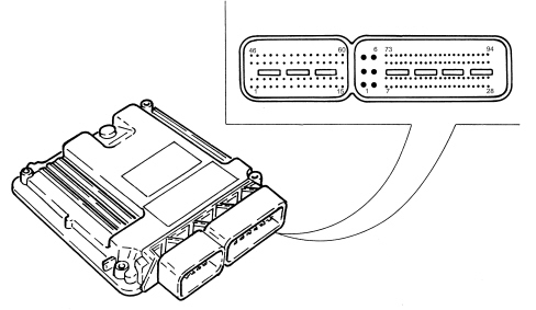
ENGINE SIDE (60-WAY) CONNECTOR
1. Cylinder 3 coil (pin 4)
2. n.c.
3. n.c.
4. INLET phase transformer L.S. signal
5. n.c.
6. n.c.
7. Fuel pressure sensor and timing sensor 1 and 2 negative (pin 1)
8. Signal from fuel pressure sensor (pin 2)
9. Throttle actuator negative (pin 2)
10. IP1 signal from throttle actuator (pin 6)
11. Flow meter (pin 3)
12. Flow meter (pin 5)
13. n.c.
14. n.c.
15. Throttle actuator motor positive power supply (pin 4)
16. Cylinder 4 coil (pin 3)
17. n.c.
18. Canister solenoid valve L.S. signal
19. OUTLET phase transformer L.S. signal
20. Pressure control valve
21. n.c.
22. signal from engine coolant temperature sensor
23. n.c.
24. power supply for fuel pressure sensor and timing sensor 1 and 2 (pin 3)
25. IP2 signal from throttle actuator (pin 5)
26. flow meter (pin 4)
27. flow meter (pin 1)
28. signal from insufficient engine oil pressure switch
29. n.c.
30. throttle actuator motor negative power supply (pin 1)
31. cylinder 2 coil (pin 5)
32 + cylinder 3 high pressure injector (pin 1)
33. - cylinder 3 high pressure injector (pin 2)
34. - cylinder 4 high pressure injector (pin 2)
35. + cylinder 4 high pressure injector (pin 1)
36. n.c.
37. n.c.
38. n.c.
39. n.c.
40. signal from engine rpm sensor (pin 2)
41. signal from timing sensor 1 (pin 2)
42. n.c.
43. detonation sensor signal 2 (pin 1)
44. detonation sensor signal 1 (pin 2)
45. n.c.
46. cylinder 1 coil (pin 6)
47. + cylinder 2 high pressure injector (pin 1)
48. - cylinder 2 high pressure injector (pin 2)
49. - cylinder 1 high pressure injector (pin 2)
50. + cylinder 1 high pressure injector (pin 1)
51. n.c.
52. n.c.
53. n.c.
54. n.c.
55. signal from engine rpm sensor (pin 1)
56. signal from timing sensor 2 (pin 2)
57. n.c.
58. detonation sensor 2 (pin 2)
59. detonation sensor 1 (pin 1)
60. n.c.
VEHICLE SIDE (94-WAY) CONNECTOR
1. earth
2. earth
3. primary load power supply
4. earth
5. primary load power supply
6. primary load power supply
7. n.c.
8. petrol pump relay positive control
9. n.c.
10. n.c.
11. H.S. A/C Req signal from NCL
12. compressor relay on CVM L.S. negative
13. n.c.
14. signal from brake lights control (NA)
15. n.c.
16. air conditioning linear pressure sensor negative
17. n.c.
18. n.c.
19. n.c.
20. signal from brake lights control (NC)
21. n.c.
22. n.c.
23. n.c.
24. n.c.
25. L.S. negative control for main relay on CVM
26. n.c.
27. n.c.
28. n.c.
29. n.c.
30. n.c.
31. n.c.
32. n.c.
33. negative from clutch pedal switch (NA)
34. Cruise control +/set signal from steering column switch unit
35. activation signal cruise control ON from steering column switch unit
36. n.c.
37. n.c.
38. air conditioning linear pressure sensor signal
39. n.c.
40. n.c.
41. n.c.
42 n.c.
43. Cruise control signal from steering column switch unit
44. n.c.
45 n.c.
46 n.c.
47. n.c.
48 n.c.
49 n.c.
50. planar Lambda sensor 1 (downstream of cat) (pin 3)
51. linear Lambda sensor 2 (upstream of cat) (pin 3)
52. planar Lambda sensor 2 (downstream of cat) (pin 2)
53. planar Lambda sensor 2 (downstream of cat) (pin 1)
54. n.c.
55. linear Lambda sensor 1 (upstream of cat) (pin 2)
56. linear Lambda sensor 1 (upstream of cat) (pin 1)
57. linear Lambda sensor 2 (upstream of cat) (pin 2)
58. linear Lambda sensor 2 (upstream of cat) (pin 1)
59. accelerator pedal potentiometer negative
60. signal from accelerator pedal potentiometer
61. Accelerator pedal potentiometer power supply
62. n.c.
63. C-CAN H
64. C-CAN H
65. n.c.
66. n.c.
67. INT/1 from F-16 CVM 7.5A
68. L.S. control for M.I. warning light in NQS
69. n.c.
70. L.S. relay negative control on CVM for engine cooling fan high speed
71. n.c.
72. n.c.
73. linear Lambda sensor 1 (upstream of cat) (pin 3)
74. planar Lambda sensor 1 (downstream of cat) (pin 2)
75. planar Lambda sensor 1 (downstream of cat) (pin 1)
76. n.c.
77. linear Lambda sensor 1 (upstream of cat) (pin 6)
78. linear Lambda sensor 1 (upstream of cat) (pin 5)
79. linear Lambda sensor 2 (upstream of cat) (pin 5)
80. linear Lambda sensor 2 (upstream of cat) (pin 5)
81. accelerator pedal potentiometer negative
82. signal from accelerator pedal potentiometer
83. accelerator pedal potentiometer power supply
84. n.c.
85. C-CAN L
86. C-CAN L
87. K line
88. n.c.
89. L.S. relay negative control on CVM for engine cooling fan low speed
90. n.c.
91. n.c.
92. +30 from F-18 CVM 7.5A
93. W line
94. planar Lambda sensor 2 (downstream of cat) (pin 3)
Injectors
They are fitted directly on the cylinder head and are operated by the engine management control unit. They are secured by means of a "fork" type fastening secured to the head by a special nut.
The injectors have a single opening with the fuel sprayed at an angle of 60° in relation to the injector.
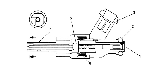
1. Fuel inlet
2. O - Ring seal
3. Electrical connection
4. Teflon seal
5. Armature
6. Coil
Pressure pump
It is the radialjet type with three radial pistons and is operated by the exhaust side camshaft by means of a special spacer.
When the engine has been started the fuel pressure in the rail is about 50 bar during idling.
The pressure in the rail can reach a maximum of 100 bar during operation depending on the engine load conditions.
The maximum pressure produced by the pressure pump is around 120 bar (if the pressure regulator is stuck).
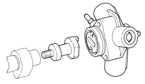
Because the pressure pump must be fed at a pressure of at least 3.5 bar, the fuel system is equipped with an auxiliary fuel pump submerged in the tank.
The pressure pump is lubricated and cooled by the fuel via special channels.
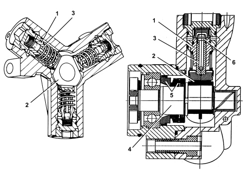
1. Cylinder
2. Cam
3. Piston
4. Pump shaft
5. Dynamic seal
6. Single-acting valve
Engine coolant temperature sensor
It is fitted on the thermostatic cup and incorporates the sensitive elements (2 NTC) in a single body which tranform the variations in temperature into variations in resistance thereby allowing the temperature of the engine coolant to be measured.
The sensor is designed using semiconductor technology. In other words, if the temperature of the sensor increases as the temperature of the coolant increases, the resistance value decreases.
Because the resistance does not change in linear fashion as the temperature increases, it is relatively higher at low temperatures than at high temperatures.
The following functions are involved with the sensor:
- information on the temperature of the coolant to the engine management control unit;
- information for the instrument panel to provide a reading for the driver.
The NTCs connect the sensor casing to an insulated earth therefore the sensor has a four-way electrical connection.
The engine coolant temperature sensor also informs the climate control system control unit.
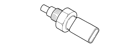
Detonation sensor
The piezoresistive type detonation sensor is fitted on the crankcase between and measures the intensity of vibrations caused by knock in the combustion chambers.
The piezoresistant crystal in the sensor detects vibrations generated at frequencies between 12 and 16 Hz and converts them to electrical signals that are sent to the injection control unit.
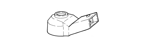
Rpm sensor
The sensor is fitted on the cylinder block/crankcase facing the flywheel on the crankshaft.
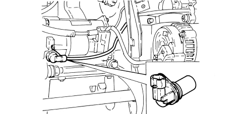
Operation
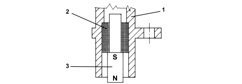
The sensor takes the form of a tubular case (1) containing a permanent magnet (3) and an electrical winding (2).
Due to the passage of the phonic wheel teeth, the magnetic flux set up by magnet (3) undergoes fluctuations due to changes in the gap.
These fluctuations set up an electromotive force in winding (2) and a voltage is set up at the terminals that is alternatively positive (tooth facing sensor) and negative (gap facing sensor).
The rpm sensor peak output voltage depends, all else being equal, on the distance between the sensor and the phonic wheel teeth (gap).
Timing sensor
The timing sensor, one for each camshaft, is the Hall effect type where a matching element and a 3 pin connector and a magnet and a signal acquisition circuit are incorporated. There are two sensors, one for each camshaft.
Accelerator pedal with integrated potentiometer
The sensor consists of a casing secured to the accelerator pedal; the case contains an axially-located shaft connected to two potetiometers: a main one and one safety one.
The engine management control unit implements the following recovery strategies:
- if one of the two potentiometers fails, this allows the throttle to be opened to a maximum of 25% over a long time period;
- if there is a total failure of the two potentiometers or a failure of one potentiometer and the brake pedal switch, the opening of the throttle is excluded.
A coil spring on the shaft ensures the correct amount of resistance to pressure while a second spring ensures return following release.
Operation
The accelerator pedal position is converted into an electrical voltage signal and sent to the injection control unit by the potentiometer connected to the pedal.
The accelerator pedal position signal is processed together with the information relating to the engine rpm to obtain the injection times and the fuel pressure.
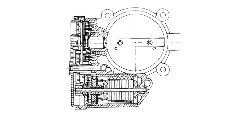
Throttle casing with d.v.l.
This is fitted on the air chamber and regulates the amount of air taken in by the engine.
According to the signal received from the accelerator pedal potentiometer, the engine management control unit controls the throttle opening by means of a direct current motor built into the integrated throttle body with D.V.L.
Throttle opening takes place from 0° to 80°, i.e. including idle speed adjustment range.
The DVL integrated throttle body is equipped with two built-in potentiometers, each of which controls the other.
If both potentiometers should fail or in the case of a power cut, the control unit reduces drive torque on the basis of accelerator pedal position.
- with the accelerator pedal fully depressed, it cuts off fuel to one or more cylinders until a maximum speed of 2500 rpm is reached;
- in the intermediate positions, it cuts off the supply to one or more cylinders until a speed below 2500 rpm is reached.
The self-learning procedure must be carried out if the injection control unit or the air chamber or the throttle casing integrated with D.V.L, is replaced.
Air flow meter
The flow meter is incorporated in the air filter casing cover and it is the heated film type.
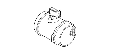
The intake air temperature sensor is built into the flow meter.
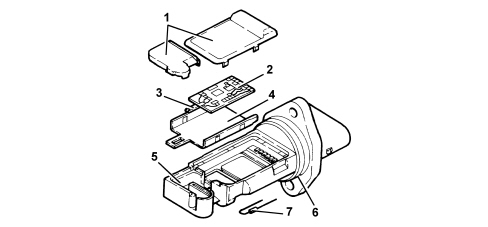
1. Covers
2. Electronic card
3. Sensor
4. Support plate
5. Support
6. O - Ring seal
7. Temperature sensor
The air flow meter cannot be disassembled.
Operation
The principle of operation is based on a heated membrane positioned within a measurement channel that carries air into the engine.
The hot film membrane is maintained at constant temperature (about 120°C higher than the incoming air temperature) by the heating coil.
The air mass that flows through the measurement channel tends to remove heat from the membrane. Current must therefore flow through the coil to maintain the membrane at a constant temperature.
This current is measured by a special Wheatstone bridge.
The current is therefore proportional to the flowing air mass.
The flow meter measures the air mass directly (not the volume) to eliminate problems of temperature, altitude, pressure etc.
Introduction
The 3.2 V6 JTS engine features a fuel feed system with a high pressure pump for direct injection.
An electronic control system supervises and governs all engine parameters to optimise performance and fuel consumption by means of a real-time response to different service conditions.
The system is managed by a single control unit - a Bosch Motronic MED 7.6.2. with motorised throttle - which controls both the ignition and the sequential, phased injection.
Depending on the signals received from numerous sensors, the control unit controls the injectors connected to it managing the following systems:
- fuel supply;
- ignition;
- high pressure fuel pump control;
- air supply;
- accelerator pedal;
- engine cooling;
- exhaust with catalytic converters controlled by four Lambda sensors;
- fuel vapour recirculation.
The control unit for this JTS engine manages the operation of the high pressure fuel pump controlling the flow rate regulator and monitoring the pressure reached by means of a sensor located on the right bank rail.
The throttle body is also controlled electronically by the control unit: the throttle opening is calculated in accordance with a specific logic inside the engine management control unit. In this way, in addition to there being no mechanical connection between the accelerator pedal and the throttle casing, the control unit is capable of managing the actual quantity of fuel required at any time the engineis operating controlling the pressure of the fuel and the starting point of the injection.
The control unit also controls the four phase transformers to ensure optimum engine response in all operating conditions.
The main system functions are essentially as follows:
- self-learning;
- system self-adaptation;
- recognition of the Alfa Romeo CODE (immobilizer);
- cold starting check control;
- control of combustion - Lambda sensors;
- detonation control;
- control of enrichment during acceleration;
- fuel cut-off when accelerator pedal is released;
- fuel vapour recovery;
- control of maximum rpm;
- fuel pump control;
- connection with climate control system;
- cylinder position recognition;
- control of optimum injection time for each cylinder;
- adjustment of ignition advance;
- idle speed management (also dependent on battery voltage);
- fan control;
- connection with ABS/VDC control unit;
- fuel system diagnostics;
- phase transformer management.
Injection system diagram
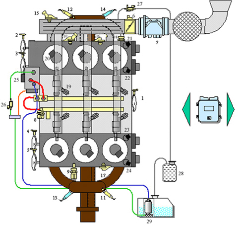
1. Rpm and TDC sensor
2. Left cylinder head exhaust camshaft timing sensor
3. Left cylinder head inlet camshaft timing sensor
4. Right cylinder head inlet camshaft timing sensor
5. Right cylinder head exhaust camshaft timing sensor
6. Throttle body
7. Flow meter (with intke air temperature sensor)
8. Fuel pressure sensor
9. Oil level and temperature sensor
10. Water temperature sensor
11. Lambda sensor upstream of pre-catalyzer, right bank
12. Lambda sensor upstream of pre-catalyzer, left bank
13. Lambda sensor downstream of catalyzer, right bank
14. Lambda sensor downstream of catalyzer, left bank
15. Absolute pressure sensor
16. Detonation sensor, left bank
17. Detonation sensor, right bank
18. Oil pressure sensor
19. Injectors
20. Coils
21. Exhaust camshaft phase transformer solenoid, left cylinder head
22. Inlet camshaft phase transformer solenoid, left cylinder head
23. Inlet camshaft phase transformer solenoid, right cylinder head
24. Exhaust camshaft phase transformer solenoid, right cylinder head
25. Flow rate regulator
26. Shut-off solenoid valve
27. Fuel vapour solenoid valve
28. Canister
29. Low pressure pump in tank
Diagram showing information entering/leaving the engine management control unit
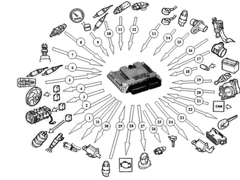
1. Injectors
2. Fuel pump
3. Air conditioning compressor
4. Engine cooling fan
5. Cruise control system control (4 digital inputs)
6. Lambda sensor downstream of the catalytic converter
7. Air conditioning system gas pressure linear sensor
8. Brake pedal switch
9. Speedometer signal detected by CAN
10. Lambda sensor upstream of the catalytic converter
11. Coolant temperature sensor
12. Timing sensors
13. Detonation sensors
14. Fuel pressure sensor
15. Rpm sensor
16. Accelerator pedal potentiometer
17. Air flow meter with built in air temperature sensor
18. Battery
19. Clutch pedal switch
20. Motorized throttle body
21. CAN line
22. Alfa CODE
23. Diagnostic socket
24. Fuel vapour recirculation solenoid valve
25. Ignition coils
26. Absolute pressure sensor
27. Phase transformer control valves
28. Injection warning light (MIL EOBD amber yellow)
29. Oil pressure sensor
30. Shut-off solenoid valve
31. Hhigh pressure flow rate regulator
Bosch MED 7.6.2 control unit operating logics
Management of the phase transformers
The variable timing on the 3.2 JTS engine is the continuous regulation type and is applied to both the inlet camshafts and the exhaust camshafts.
The overall adjustment range (inlet and exhaust) is 50 degrees and the controls between the inlet and exhaust sides are completely independent of one another.
With the engine idling, both camshafts are in the "park" position; in this situation the exhaust camshafts are fully advanced and the inlet camshafts fully delayed and they remain like this during starting. This timing configuration guarantees the minimum crossover between the inlet and exhaust valves.
The pins that lock the camshafts in the basic position ensure that they are in the correct position on starting and that there is no noise due to the uncontrolled rotation of the rotor in relation to the stator. To allow the movement of the phase transformer a certain operating pressure must be reached in order to release the pin locking the transformer in the basic position and allowing movement.
Depending on the engine position, it is possible from the basic position to control the advance of the inlet camshafts and the delay of the exhaust camshafts within a maximum rotation range of 50 degrees for each shaft; what is of fundamental importance is that this system makes it possible to control all the intermediate positions for the shafts within the above mentioned range so that the best engine working conditions can be produced for all speed and load conditions.
Timing diagram variation
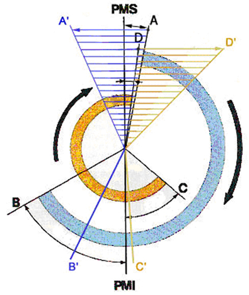
A - Inlet shaft basic fitting position (completely delayed)
B - Exhaust shaft basic fitting position (completely advanced)
A'' - Maximum rotation in relation to inlet shaft position
B'' - Maximum rotation in relation to exhaust shaft position
Thanks to the intervention of the phase transformers, the timing diagram can be altered as can be seen in the diagram above; in particular, the opening advance for the inlet valves can move inside the area defined by the line A and the line A'', whilst the closing delay for the exhaust valves can move inside the area definied by the line B and the line B''.
The action of the phase transformers is therefore principally understood as controlling the opening advance of the inlet valves and the closing delay of the exhaust valves. Obviously the variation in the opening advance of the inlet valves also produces a variation in their closing point in the same way as the variation in the closing delay of the exhaust valves also produces a variation in the opening point.
The maps used for the management of the timing diagram are a compromise between the opening advance and closing delay for both the inle and exhaust valves in terms of ensuring optimum consumption, performance and emissions.
The control unit, depending on the information received concerning the following:
- the engine temperature;
- the engine speed;
- the engine load;
- the position of the accelerator pedal;
- the Lambda sensor signals.
manages the phase transformers independently, continuously controlling the four proportional control solenoid valves to ensure careful management of the timing for the best control of the emissions and the torque supplied by the engine.
Alfa code recognition
The moment the control unit receives the ignition ON signal it converses with the Body Computer, via the ALFA CODE function, to give the enablement for starting.
Self-learning
- installation of a new injection control unit,
- installation of a new throttle body actuator,
- removing-refitting or replcing the rpm/flywheel sensor for the recognition of misfire.
The learning values for the throttle body are maintained with the battery disconnected.
The learning values for the flywheel for recognizing misfire, on the other hand, are lost.
System self-adjustment
The control unit is equipped with a self-adjustment function that is designed to recognize the changes that take place in the engine due to the processes of bedding in and ageing of both the components and the engine itself in time.
There are two adaptive functions depending on the two intervention plans: minimum and utilization.
Cold starting check
In cold starting conditions the mixture is naturally weakened causing low evaporation of the fuel at low temperatures and increased viscosity of the engine lubricant.
The electronic control unit detects this condition and corrects the injection time on the basis of:
- coolant temperature;
- intake air temperature;
- battery voltage;
- engine rpm.
The ignition advance is determined solely on the basis of rpm and coolant temperature.
During the start-up stage, the control unit sends an initial simultaneous injection command to all injectors (full-group injection). Once cylinder phase has been detected, normal phased sequential operation can begin.
Whilst the engine is warming up, the control unit operates the throttle body to regulate the quantity of air required to ensure that the engine speed is sustained.
The rotation speed is made to decrease with increasing temperature until the rated level is reached with the engine warm.
Control of combustion - lambda sensors
In EOBD systems the Lambda sensors are located upstream of the catalyzer system and downstream of the catalyzer.
The upstream sensors control the mixture strength and are known as the upstream sensors closed loop. The sensors downstream of the catalytic converter are used to for converter diagnostics and to fine-tune 1st loop control parameters.
The adaptation of the second loop is designed to recover both production losses and the slackening that occurs in the upstream sensors as a result of ageing and pollution.
This control is known as the 2nd downstream sensors closed loop.
Detonation control
The control unit can delay ignition, selectively at the cylinder where it is required, depending on a combination of values received by the detonation and timing sensors and:
- reduces the ignition advancesin steps of 3° up to a maximum of 12°;
- updates the threshold value to take into account background noise and the ageing of the engine.
During acceleration the control unit uses a higher threshold for the increased engine noise.
When the detonation disappears, the control unit increases the ignition advance in steps of 0.75 degrees until the recovery is complete.
The control unit with a self-adaptive function:
- stores advance reductions that are repeated continuously;
- adjusts mapping to the various different engine service conditions.
RECOVERY
If the detonation sensor is faulty, an ignition advance delay that varies according to the engine speed or temperature is implemented. Maximum ignition delay is always less than 6° engine.
Control of enrichment during acceleration
In cases of high acceleration demand, the control unit modifies injection time and throttle position.
RECOVERY
The control unit replaces the signal coming from the faulty air flow meter with the signal for the potentiometer built-into the throttle casing actuator.
Fuel cut-off when the accelerator pedal is released
The control unit with:
- detection of idling status;
- rpm above a certain threshold;
deactivates the fuel injection in the following cases:
- engine speed below 1500 rpm;
- engine temperature below 40 °C;
Before reaching idling level, the rpm descent rate is assessed. If it is above a certain level, the fuel injection is partly reactivated according to a logic that involves the gentle accompaniment of the engine at idle speed.
Once idling speed has been reached, normal functions are resumed.
Fuel vapour recovery
The fuel vapours, coming from the active charcoal filter (canister), are sent to the intake ducts to be burnt.
This takes place by means of a solenoid valve operated by the control unit which alternates phases in which it is open (canister scavenging stage) with phases in which it is closed (carburation learning stage).
During the opening phases, the solenoid valve opening duty-cycle is regulated by the control unit to eliminate the fuel vapours without altering the engine carburation.
Control of maximum rpm
According to the rpm level reached by the engine, the control unit:
- beyond 7200 rpm removes the supply from the injectors (dynamic control of maximum speed)
- after having checked the maximum speed with the dynamic control, carries out the maintenance by adjusting the position of the motorized throttle independently of the request coming from the accelerator pedal potentiometer (idle static control); this makes it possible to control the maximum speed keeping oscillations from the fuel cut off to a minimum.
Fuel pump control
The control unit:
- supplies the electric fuel pump with the ignition ON (for 5 seconds)
- supplies the pump with the ignition in the starting position and the engine speed above 25 rpm;
- interrupts the supply to the pump with the ignition OFF or the engine speed below 25 rpm
Connection with climate control system
The compressor takes up power from the engine when the climate control system is activated.
In idling conditions, the control unit adapts the air flow rate to the new power requirements with the advantage of maintaining optimum driveability.
The control unit manages the exclusion of the compressor:
- if there is insufficient climate control system gas pressure;
- above a set engine coolant temperature threshold (117 °C);
- during starting;
- in low rev conditions.
There is no exclusion for maximum power request.
Recognition of cylinder position
The control unit recognizes which cylinder is in the explosion stroke by means of the engine rpm and TDC sensor and the timing sensors: it controls the injection and ignition sequence for the cylinder in a sequential, timed fashion.
Check on optimum injection time for each cylinder
The injection start angle varies from –250° to –340° to allow a homogonized mixture and optimum combustion in all engine operating conditions.
Idle speed management
The control unit detects idling status when the accelerator pedal is released.
The control unit regulates the idle speed value depending on the engine temperature and battery voltage.
Fan control
The control unit controls the engagement of the fan depending on the temperature of the coolant:
- temperature for engaging first speed: 98 °C;
- temperature for engaging second speed: 106 °C.
If the air conditioning system is on, the control unit controls the engagement of the first speed.
If there is no coolant temperature signal, the control unit implements the recovery function engaging the second speed until the error disappears.
Before the activation of the fans, the throttle opening is increased to prevent the engine revs from falling.
Connection with abs/vdc control unit
The dialogue between the engine management control unit and the ABS/VDC control unit takes place via the C-CAN line.
If the wheels are slipping (signalled by the ABS/VDC control unit), the engine management control unit reduces the engine torque by:
- reducing the ignition advance;
- reducing the throttle opening angle;
- reducing the injection time.
SPECIFICATIONS
4 cylinder in line engine, sequential, phased type integrated injection and ignition system, 16 valves, dual overhead camshaft, continuous adjustment through phase transformer, motorized throttle body; equipped with Simtec 75.3 injection system and control unit produced by Siemens VDO.
The unit is a system made up of the engine and all circuits required for its operation:
- fuel supply system
- air supply system
- engine cooling system
- exhaust system with catalytic converter built into the exhaust manifold
- fuel vapour recirculation system.
The operation of these systems is optimised by an electronic control system governed by a control unit.
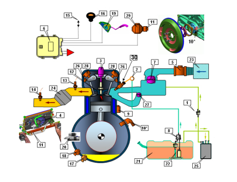
1. Fuel vapour flow enablement solenoid
2. Single fuel manifold
3. Ignition coil module
4. Radiator
5. Air flow meter
6. Injection/ignition control unit
7. Throttle body
8. Fuel filter
9. Detonation sensor
10. Rpm sensor
11. Coolant temperature sensor on radiator
12. Spark plugs
13. Upper Lambda sensor
14. Lower Lambda sensor
15. Diagnostic connector
16. EOBD warning light
17. Oil level sensor
18. Oil pressure switch
19. Accelerator pedal
20. Starter motor
21. Fuel tank
22. Fuel pressure regulator
23. Air filter
24. Catalytic converter
25. Activated charcoal filter (canister)
26. Timing sensor
27. Variable geometry chamber solenoid
28. Phase transformer solenoid
29. Electrical thermostat adjustment
30. Injector
Operation of the injection system - ignition
The Simtec 75.3 system with a motorized throttle manages the sequential, phased type electronic injection and ignition function.
The control unit controls the air flow rate at the idling speed set by the electronic throttle.
The control unit controls the ignition time, with the benefit of maintaining smooth engine operation even when environmental and applied load parameters and engine operating conditions change.
The control unit controls and manages the injection so that the air/fuel ratio is always close to the stoichiometric ratio to ensure maximum conversion efficiency for the catalytic converter.
The main system functions are essentially as follows:
- self-learning;
- system self-adaptation;
- autodiagnosis on K line;
- recognition of Alfa CODE (Immobilizer) on the CAN serial line;
- cold starting control;
- control of combustion - Lambda sensors;
- check on phase transformers and modular intake manifold;
- detonation control;
- control of mixture enrichment during acceleration;
- fuel cut-off during release of accelerator pedal;
- fuel vapour recovery;
- control of maximum rpm;
- fuel pump control;
- climate control system control;
- cylinder position recognition;
- control of optimum injection time for each cylinder;
- adjustment of ignition advance;
- idle speed management (also dependent on battery voltage - electrical balance management function);
- management of throttle opening laws (accelerator pedal - torque request maps);
- 3 speed fan control;
- connection with ABS/ASR/VDC control unit;
- cruise control (where fitted);
- connection with the control panel;
- torque management;
- control of engine coolant temperature by means of electrically adjusted thermostat
EOBD OPERATION:
- fuel system diagnostics;
- catalytic converter diagnostics;
- misfire diagnosis; detection of failed combustion;
- Lambda sensor diagnosis (pollution or signal distortion).
Torque control strategy
The drive-by-wire control systems are vital in satisfying the legal requirements such as those regarding fuel consumption and emissions, as well as for improving the driveability of vehicles with petrol engines (starting, heating, dynamic transition response, safe driving).
The torque for petrol engines is mainly affected by the throttle valve which controls the mass of air introduced by the engine, (depending on the position of the accelerator pedal; more precisely, the request for torque by the user, coming from the accelerator pedal, does not directly control the opening of the throttle valve, as in traditional systems with mechanical bowden cables, but is processed electronically by the control unit before being implemented by the throttle electric motor), and therefore also the filling of the cylinder.
In addition to this there are other parameters that affect the variation of the engine torque: the ignition angle, the air/fuel (Lambda) ratio, the deactivation of injection for some cylinders.
INJECTION SYSTEM
The essential conditions to be met by the air-fuel mixture for efficient operation of engines with controlled ignition systems are mainly as follows:
- the metering (air/fuel ratio) must be kept as close as possible to the stoichiometric value to ensure maximum catalytic converter conversion capacity (max. efficiency).
- the homogeneity of the mixture, consisting of petrol distributed throughout the air as finely and uniformly as possible.
Information that the control unit processes to control optimum metering is received by electrical signals emitted by:
- air flow meter (debimeter) and (built in) air temperature sensor, for the exact quantity of air taken in
- rpm sensor, which produces the digital signals created by the variations in the magnetic field (Hall effect).
The control unit uses this signal to detect MISFIRE.
- throttle potentiometer, to recognize the accelerator request conditions (the dual throttle potentiometer is, in reality, a safety feature of the DbW system and has the main function of monitoring the effective position of the throttle valve controlled by the activating motor, in particular during the management of possible fault conditions and the implementation of recovery strategies).
The torque request information by the driver is recognized by the control unit by means of the accelerator pedal dual potentiometer.
- coolant temperature sensors located on the thermostat and the radiator outlet;
- Lambda sensors to determine the oxygen content of the exhaust gases and, via the downstream sensor, to diagnose the efficiency of the catalytic converter.
IGNITION SYSTEM
The ignition system is the static, inductive discharge type (i.e. without a high voltage distributor).
The ignition system has a single coil for each spark plug with an integrated power stage.
The advantages of this solution are:
- lower electrical overload;
- guaranteed constant discharge at each spark plug.
The control unit contains a memory map with a set of optimum ignition advance values (for the cylinder in combustion phase) that the engine can adopt according to the required speed and engine load.
The control unit corrects the advance value mainly on the basis of:
- engine coolant temperature
- intake air temperature
- detonation.
- throttle valve position.
Information that the control unit processes to operate the single coils is received by electrical signals emitted by:
- air flow meter (debimeter) with built in air temperature sensor, for the exact quantity of air taken in;
- rpm sensor;
- detonation sensor (on the rear part of the crankcase between cylinders 2 and 3) to recognise the cylinder with knock and thus correct the ignition advance;
- throttle position potentiometer to recognise minimum, partial and full load conditions.
- timing sensors.
The control unit uses the rpm signal to recognize misfiring that could damage the catalytic converters.
DIAGRAM SHOWING INFORMATION ENTERING/LEAVING THE CONTROL UNIT
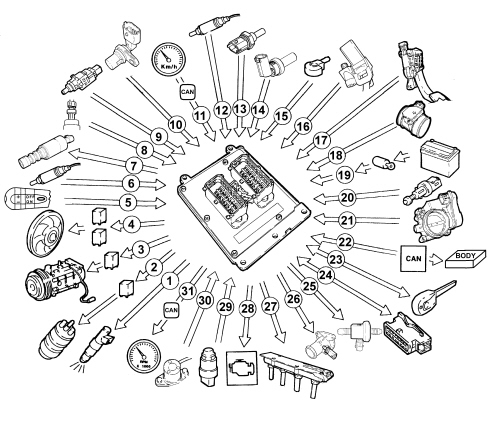
1. Injectors
2. Fuel pump
3. Air conditioning compressor
4. 3 speed fan
5. Cruise control lever
6. Lambda sensor downstream of the catalytic converter
7. Phase transformer solenoid
8. Air conditioning system freon pressure linear sensor
9. Brake pedal switch
10. Timing sensor
11. Speedometer signal detected by CAN
12. Lambda sensor upstream of the catalytic converter
13. Coolant temperature sensor (on the radiator)
14. Coolant temperature sensor (on the thermostat)
15. Detonation sensor
16. Rpm sensor
17. Accelerator pedal potentiometer
18. Air flow meter with built in air temperature sensor
19. Battery
20. Clutch pedal switch
21. Motorized throttle body
22. CAN line
23. Alfa CODE (on CAN and on redundant W line)
24. Diagnostic socket
25. Fuel vapour recirculation solenoid
26. Resistance for electrically controlled thermostat
27. Ignition coils and external power module
28. Injection warning light
29. Oil pressure switch
30. Oil level switch
31. Engine rpm signal detected by CAN
SYSTEM OPERATING LOGICS
Self-learning
The control unit implements the self-learning logic in the following conditions:
- removing-refitting or replacement of the injection control unit;
- removing-refitting or replacing the integrated throttle casing;
The Simtec 75.3 ECU carries out the throttle body learning procedure automatically at the next key-on.
The values stored by the control unit are maintained when the battery is disconnected.
System self-adjustment
The control unit is equipped with a self-adjustment function that is designed to recognise the changes that take place in the engine due to the processes of bedding in and ageing over time of both the components and the engine itself.
These changes are memorised in the form of modifications to the basic map and are designed to adapt the operation of the system to the gradual alterations in the engine and the components compared with when they were new.
This self-adjustment function also makes it possible to compensate for the inevitable differences in any replacement components (owing to production tolerances).
The control unit modifies the basic map in relation to engine specifications when new, on the basis of exhaust gas analysis.
The self-adjustment parameters are not deleted if the battery is disconnected.
Self-diagnosis
The control unit auto-diagnostic system checks that the system is working properly and signals any irregularities by means of an (MIL) warning light in the instrument panel with a standardised ideogram and colour, as stipulated by European regulations. This warning light indicates engine management faults and also faults detected by EOBD diagnostic strategies.
The MIL warning light operating strategy is as follows:
- with the ignition on, the warning light comes on and remains on until the engine has been started up. The control unit self-diagnostic system checks the signals coming from the sensors and compares them with the permitted limits.
Fault indication during start up:
- the failure of the warning light to go out when the engine has been started indicates that there is an error memorised in the control unit.
Fault indication during operation:
- the warning light comes on in flashing mode to indicate possible catalytic converter damage due to misfiring.
- the warning light comes on in constant mode to indicate the presence of engine management or EOBD diagnostic errors.
Not all faults lead to the MIL EOBD warning light coming on. The effective presence of faults should be checked by reading the control unit errors memory with the diagnostic socket on the K line.
Recovery
From time to time the control unit defines the type of recovery according to the components that are faulty.
The recovery parameters are managed by components that are not faulty.
Alfa code recognition
The moment the control unit receives the ignition ON signal it converses with the Alfa CODE control unit (via the body computer on the CAN serial line to obtain the go ahead for starting.)
Cold starting control
The following occurs in cold starting conditions:
- a natural weakening of the mixture as a result of poor evaporation of the fuel at low temperatures;
- fuel condensation on inner walls of the intake manifold;
- increased lubrication oil viscosity.
The electronic control unit detects this condition and corrects the injection time on the basis of:
- coolant temperature;
- intake air temperature;
- battery voltage;
- engine rpm.
The ignition advance is determined solely on the basis of rpm and coolant temperature.
Whilst the engine is warming up, the control unit operates the motorized throttle to regulate the quantity of air required to ensure that the engine does not cut out.
The rotation speed decreases proportionally as the engine temperature increases, until the nominal value is reached when the engine has warmed up.
Control of combustion - lambda sensors
In EOBD systems, the Lambda sensors are all the same type and are located upstream of the catalytic conversion system and downstream of the converter. The upstream sensors monitor concentration and are known as the 1st loop (closed loop of upstream sensor). The sensor downsream of the catalytic converter is used for the fault diagnosis of the catalytic converter (in the Simtec 75.3 system the downstream sensor is only used to carry out the catalytic converter fault diagnosis).
Control of the phase transformer and modular intake manifold
In order to ensure the optimum quantity of air introduced by the engine, the control unit controls:
- continuous intake and exhaust timing;
- the geometry of the intake manifolds in two lengths.
At maximum torque the control unit controls the intake manifold in the the long duct position.
At maximum power and idle the control unit controls the intake manifold in the short duct position.
In all other engine operating conditions, the control unit selects the most suitable configuration for optimum performance, consumption and emissions.
Control of detonation
The control unit detects the presence of detonation (engine knock) by processing the signal coming from the relevant sensor.
The control unit continuously compares the signals coming from the sensor with a threshold which is, in turn, continually updated to take into account background noise and engine ageing.
The control unit is therefore capable of detecting the presence of detonation (or the onset of detonation) in each individual cylinder and reduces the ignition advance in the cylinder involved (in steps of 3° up to a maximum of 6°) until the phenomenon disappears. Later on, the advance is gradually restored to the basic value (in steps of 0.8°).
In acceleration conditions, a higher threshold is used to take into account the increased noise of the engine in these circumstances.
The detonation control logic also has a self-adjustment function which memorizes the reductions in the advance that are continuously repeated in order to adapt the map to the different conditions affecting the engine.
Control of enrichment during acceleration
If, during the acceleration request, the variation in the air flow meter signal exceeds a pre-set level, the control unit increases the injection (time) to compensate for the variation in the mixture ratio due to the increased pressure in the intake manifold (less fuel evaporation): this allows the required engine speed to be reached more quickly.
Recovery
The control unit replaces the signal coming from the air flow meter which is faulty, with the throttle potentiometer signal.
Fuel cut off during deceleration
When the accelerator pedal is released and beyond a pre-set engine speed level, the control unit:
- cuts off the supply to the injectors
- reactivates the supply to the injectors at 1400 - 1500 rpm
If there is no supply, the number of revs decreases with the speed, depending on the vehicle driving conditions.
Before the idle speed is reached, the progress of the engine speed decrease is checked.
If it is above a certain value, the fuel supply is partly restored so that there is a "gentle accompaniment" towards the idle speed.
The level for restoring the supply and for cutting off the fuel varies according to:
- engine coolant temperature;
- gear engaged;
- engine rpm.
Fuel vapour recovery
Fuel vapours (pollutants) collected in the activated carbon filter (canister) are directed to the intake ports to be burnt.
This takes place by means of a solenoid controlled by the control unit only when the engine operating conditions allow.
The control unit compensates for this additional amount of fuel with a reduction in the supply to the injectors.
Control of the maximum revs
According to the rpm level reached by the engine, the control unit:
- beyond 6500 rpm the throttle is restricted not to exceed this level;
- below 6500 rpm, normal throttle operation is resumed.
Control of fuel supply - electric fuel pump
The control unit supplies the pump:
- with the ignition ON for 3 secs.;
- with the ignition on START and the engine speed above 32 rpm.
The control unit cuts off supply to pump:
- with the ignition key in the OFF position;
- with the engine speed below 32 rpm.
The "returnless" fuel supply system ensures a constant fuel pressure of 3.8 bar.
Connection with the climate control system
When there is a request for power, due to the compressor being switched on, the control unit adjusts the air flow rate with the advantage of maintaining optimum driveability.
The control unit momentarily cuts off the supply to the compressor:
- during starting
- over 6000 rpm
- with the engine temperature above 120 °C
- during take off (depending on the engine speed, pedal position and vehicle speed.)
Recognition of cylinder position
During each engine revolution, the control unit detects the cylinder in combustion phase through the timing sensors: it controls the injection and ignition sequence for the appropriate cylinder.
If the timing sensor is faulty, the control unit implements the following strategies:
- with the engine running, it ensures the engine runs correctly due to its memorized cylinder sequence;
- if the engine is turned off and restarted, the ignition is activated for coil pairs with a lost spark. Knock control is deactivated and a fixed delay is applied for all cylinders.
Adjustment of injection times
The control unit calculates the injector opening time and controls them with extreme precision and speed depending on the:
- rpm;
- air flow rate;
- battery voltage;
- engine coolant temperature.
Adjustment of ignition advances
Thanks to a map stored in its memory, the control unit is capable of calculating the ignition advance depending on:
- the engine load (minimum, partial, full, according to the number of revs and the air flow rate);
- the intake air temperature.
Control of engine cooling fan
Depending on the temperature of the coolant leaving the engine and the temperature of the coolant coming out of the radiator, the control unit controls the engagement of the fan, if the engine cooling cannot be managed through the advance opening of the electrically controlled thermostat.
There are 3 possible speeds (depending on an internal map).
There is a further control (air conditioning system freon pressure analogue signal from the linear sensor) which switches on the fan. This operates in accordance with a memorized table, depending on the pressure of the refrigerant gas with the air conditioning system on.
When no coolant temperature signal is present, the control unit implements the recovery function by activating the fan at the maximum speed until the error disappears.
INJECTION-IGNITION SYSTEM COMPONENTS
Injection-ignition control unit
The control unit is fitted on the intake manifold and withstands high temperatures.
The control unit memory is the flash EPROM type, i.e. it can be reprogrammed from the outside without affecting the hardware. The adoption of the Alfa CODE (key check via the Body Computer) means that control units cannot be swapped between vehicles.
The replacement of the injection control unit does not require any specific procedure using diagnostic equipment for the learning of the motorized throttle body: this procedure takes place automatically at the key-on.
The engine management control unit is a component sensitive to electrostatic interference; avoid touching the control unit with the engine running unless you are wearing suitable clothing or have discharged any static electricity by touching something metal.
The engine compartment contains many moving parts, components at high temperatures and live wires. Follow very carefully the warnings given below when working in the engine compartment: turn off the engine and wait for it to cool down, do not smoke, do not use naked flames and ensure a fire extinguisher is available.
Control unit pin out
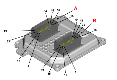
Connector A - Engine side (64 pin)
A1 - Coil control signal for cylinder 1
A2 - Coil control signal for cylinder 1
A3 - Modular intake manifold
A4 - Electronic thermostat
A5 - Insufficient engine oil pressure switch (digital input)
A6 - Downstream Lambda sensor earth
A7 - Not connected
A8 - Motorized throttle potentiometer signal 2
A9 - Motorized throttle potentiometer signal 1
A10 - Detonation sensor (positive)
A11 - Downstream Lambda sensor earth
A12 - Intake air temperature signal incorporated in the flow meter
A13 - Not connected
A14 - Not connected
A15 - Not connected
A16 - Not connected
A17 - Coil control signal for cylinder 2
A18 - Coil control signal for cylinder 2
A19 - Downstream lambda sensor heater control
A20 - Not connected.
A21 - Exhaust side timing sensor signal
A22 - Inlet side timing sensor signal
A23 - Upstream Lambda sensor earth
A24 - Inlet side timing sensor negative
A25 - Engine coolant temperature sensor negative (A)
A26 - Exhaust side timing sensor negative
A27 - Detonation sensor negative
A28 - Flow meter negative
A29 - Downstream Lambda sensor earth
A30 - Not connected
A31 - Motorized throttle actuator positive
A32 - Motorized throttle actuator
A33 - Coil control signal for cylinder 3
A34 - Coil control signal for cylinder 3
A35 - Rpm sensor signal
A36 - Not connected
A37 - Not connected
A38 - Not connected
A39 - Rpm sensor negative
A40 - Motorized throttle potentiometer negative 1
A41 - Motorized throttle potentiometer signal 2
A42 - Inlet side timing sensor positive
A43 - Not connected
A44 - Detonation sensor earth
A45 - Not connected
A46 - Fuel vapour recovery solenoid valve
A47 - Motorized throttle actuator negative
A48 - Motorized throttle actuator negative
A49 - Coil control signal for cylinder 4
A50 - Coil control signal for cylinder 4
A51 - Not connected
A52 - Not connected
A53 - Upstream Lambda sensor positive
A54 - Downstream Lambda sensor positive
A55 - Exhaust side phase transformer actuator
A56 - Inlet side phase transformer actuator
A57 - Not connected
A58 - Upstream Lambda sensor heater
A59 - Flow meter
A60 - Engine coolant temperature sensor signal (A)
A61 - Cylinder 2 injector control
A62 - Cylinder 3 injector control
A63 - Cylinder 4 injector control
A64 - Cylinder 1 injector control
Connector B - Vehicle side (64 pin)
B1 - Injection system failure warning light
B2 - Air conditioning system engagement request
B3 - Engine coolant temperature sensor signal (B) (on radiator)
B4 - Not connected
B5 - K line
B6 - CAN L line
B7 - Not connected
B8 - Not connected
B9 - Not connected
B10 - Engine cooling fan 2nd speed engagement relay
B11 - Not connected
B12 - Not connected
B13 - Not connected
B14 - Not connected
B15 - Not connected
B16 - Clutch pedal switch
B17 - Not connected
B18 - Not connected
B19 - Not connected
B20 - Not connected
B21 - CAN L line
B22 - Not connected
B23 - Sensors power supply
B24 - Motorized throttle potentiometer power supply 1
B25 - Motorized throttle potentiometer power supply 2
B26 - Motorized throttle potentiometer negative 1
B27 - Motorized throttle potentiometer negative 2
B28 - Engine coolant temperature sensor negative (B) (on radiator)
B29 - Not connected
B30 - Not connected
B31 - +30 battery power supply
B32 - +30 battery power supply
B33 - Not connected
B34 - Not connected
B35 - Not connected
B36 - Not connected
B37 - CAN L line
B38 - CAN H line
B39 - Not connected
B40 - Not connected
B41 - Cruise Control ON/OFF
B42 - Cruise Control resume
B43 - Cruise Control SET +
B44 - Cruise Control SET -
B45 - Brake light switch
B46 - Not connected
B47 - +30 battery power supply
B48 - Compressor relay
B49 - Fuel pump relay
B50 - Not connected
B51 - Not connected
B52 - Not connected
B53 - Potentiometer signal - accelerator pedal 2
B54 - Potentiometer signal - accelerator pedal 1
B55 - Not connected
B56 - Air conditioning linear pressure sensor
B57 - Brake light switch
B58 - W line
B59 - Engine cooling fan 1st speed engagement relay
B60 - Not connected
B61 - Engine cooling fan 3rd speed engagement relay
B62 - Main relay
B63 - Not connected
B64 - + 15/54 ignition-operated power supply
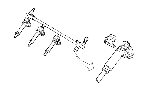
Injectors
The injectors are the twin jet type and are fitted on the injector carrier manifold.
Accelerator pedal potentiometer
The sensor consists of a casing secured to the accelerator pedal; the case contains an axially-located shaft connected to two potetiometers: a main one and one safety one.
A helical spring on the shaft ensures the correct amount of resistance to pressure while a second spring ensures return following release.
The accelerator pedal position is converted into an electrical voltage signal and sent to the control unit by the potentiometer connected to the pedal. The accelerator pedal position signal is processed together with the information relating to the engine rpm to obtain the injection times and the relatve position of the motorized throttle.

Insufficient oil pressure sensor
The sensor is located on the crankcase, engine oil dipstick side. The control unit controls the signal which is used for:
- showing the message in the multifunction display;
- switching on the warning light in the panel.
It does not switch the MIL warning light on.

Engine coolant temperature sensors
There are two engine coolant temperature sensors, one fitted on the thermostat and the other on the radiator in correspondence with the outlet hose.
Both sensors incorporate the sensitive element (1 NTC) in a single body and transform the variations in temperature into variations in resistance, thereby allowing the temperature of the engine coolant to be measured.
The sensor is designed using semiconductor technology. In other words, if the temperature of the sensor increases as the temperature of the coolant increases, the resistance value decreases.
Because the resistance does not change in linear fashion as the temperature increases, it is relatively higher at low temperatures than at high temperatures.
The sensor is involved with the following functions:
- information on the temperature of the coolant coming out of the engine to the engine management control unit;
- information on the temperature of the coolant coming out of the radiator to the engine management control unit;
- information for the instrument panel to provide a reading for the driver.
Reference voltage: 5 Volts
Operating temperature: - 40 ° - + 140 °C
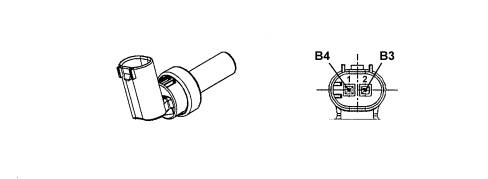
Coolant temperature sensor on the radiator
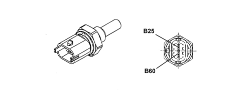
Coolant temperature sensor on the thermostat
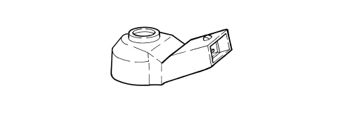
Detonation sensor
The piezoelectric type detonation sensor is fitted on the crankcase and measures the intensity of vibrations caused by knock in the combustion chambers.
The piezoresistant crystal in the sensor detects vibrations generated at frequencies between 12 and 16 Hz and converts them to electrical signals that are sent to the injection control unit.
Timing sensor
The timing sensor, one for each camshaft, is the Hall effect type where a matching element, a 3 pin connector, a magnet and a signal acquisition circuit are incorporated. There are two sensors, one for each camshaft.
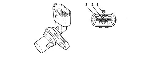
Pin out
1. Signal
2. Earth
3. Fuel system
Rpm sensor
The rpm and T.D.C. sensor is built into the flywheel side crankshaft seal.
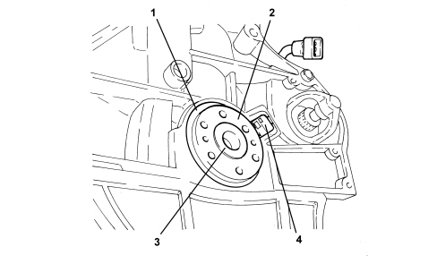
1. Crankshaft rear seal
2. Magnetized disc (encoder)
3. Crankshaft
4. Rpm and T.D.C. sensor
Operation
The crankshaft position and rpm are not transmitted to the rpm sensor by means of a toothed phonic wheel, but by a disc (encoder) (3) with an externally applied magnetized layer (4).
The inner surface of the encoder contains a projection (7) for positioning it correctly on the crankshaft.
The rpm sensor (5) can be removed from the crankshaft seal by loosening a retaining bolt (6) and detaching the connector for the cable loom from the crankshaft seal. In this way, one of the two components can be replaced, either the crankshaft seal or the rpm sensor, independently of the other one.
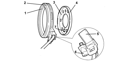
1. Crankshaft seal lip
2. Outer surface of crankshaft seal
3. Encoder
4. Encoder magnetized track
5. Rpm sensor
6. Rpm sensor retaining bolt
7. Projection for positioning encoder on crankshaft
The encoder magnetised track contains the north and south magnetic poles whose magnetic fields are recorded by the rpm sensor during the rotation of the crankshaft, and are transformed into rpm values and determine T.D.C. in the engine management control unit.
The recognition of the magnetic fields takes place in accordance with the Hall principle. The rpm sensor sends digital signals produced by the variation in the magnetic fields to the engine management control unit.
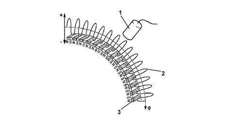
1. Rpm sensor
2. Magnetic field track
3. Rubber coating for supporting magnets
In order not to alter the magnetic specifications of the encoder, it is vital to follow the warnings given below for carrying out work on the encoder.
Maintenance warnings:
- Do not bring into contact with other magnetic fields,
- Do not bring into contact with metal shavings,
- Do not damage mechanically the encoder rubber track,
- Do not drop the encoder.
Throttle casing with d.v.l.
This is fitted on the modular air intake chamber and regulates the amount of air taken in by the engine.
According to the signal received from the accelerator pedal potentiometer, the engine management control unit controls the throttle opening by means of a direct current motor built into the throttle body with D.V.L.
Throttle opening takes place from 0° to 80°, i.e. including idle speed adjustment range.
The DVL integrated throttle body is equipped with two built-in potentiometers, each of which controls the other.
If both potentiometers should fail or in the case of a power cut, the control unit reduces drive torque on the basis of accelerator pedal position.
- with the accelerator pedal fully depressed, it cuts off the supply to one or more cylinders until a maximum speed of 1800 rpm is reached;
- in the intermediate positions, it cuts off the supply to one or more cylinders until a speed below 1800 rpm is reached.
If the throttle body with D.V.L. or the injection control unit or the modular air intake chamber is being replaced, the self-learning procedure takes place automatically at the next key-on.
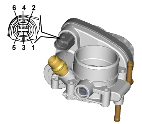
Pin out
1. Potentiometer signal
2. Potentiometer positive
3. Motorized throttle actuator
4. Potentiometer 2 signal
5. Motorized throttle actuator negative
6. Potentiometer earth
Air flow meter
The flow meter has the function of measuring the mass of air in the intake manifold; it also includes an air temperature sensor for adapting the calculation to the actual density of the intake air.
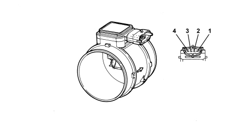
Pin out
1. Earth
2. Flow meter intake air temperature signal
3. Flow meter signal
4. Fuel system
Ignition coils
The ignition circuit is the inductive discharge static type, where the high tension is provided by four coils incorporated in a single element and fitted directly above the spark plugs.
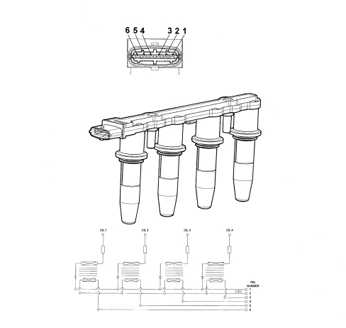
Pin out
1. Coil earth
2. Fuel system
3. Cylinder 4 coil control
4. Cylinder 3 coil control
5. Cylinder 2 coil control
6. Cylinder 1 coil control
Parts & tools for this job Staging For 2005 Alfa Romeo 159
- PARTFuel filterSearch: Alfa Romeo 159 2005 fuel filter
- TOOLFuel pressure test kitSearch: fuel pressure test kit
- TOOLFuel line disconnect toolSearch: fuel line disconnect tool
Links open Amazon search results in a new tab. As an Amazon Associate I earn from qualifying purchases.