
Fuel level gauge check
- Make
- Alfa Romeo
- Model
- 159 Factory Service Manual
- Year
- 2005–2011
- Section
- Fuel tank and pipes › Fuel level gauge check
FUEL LEVEL GAUGE CHECK
Disconnect the connection from the fuel intake assembly.
Connect using an Examiner in Ohmmeter mode to the connection for the fuel intake assembly at pins 5 and 6
Read a resistance proportional to the level of the fuel as illustrated in the table below
the tolerance of the measured resistance value is approximately 5%
| Fuel quantity [litres] | Resistance value [ohm] |
|---|---|
| 62 | >5 |
| 54 | 73 |
| 46 | 107 |
| 38 | 133 |
| 31 | 159 |
| 23 | 186 |
| 15 | 216 |
| 8 (riserve) | 248 |
| 1 | 300 |
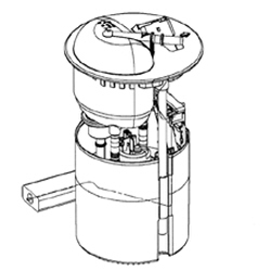
The following figure shows the fuel pump assembly
| CHECK TO BE PERFORMED | RESOLUTION IF THE CHECK IS NOT OK | |
|---|---|---|
| 1 | Check the fuel level signalled by the gauge in the panel and make a note of it. Connect to the pump connector See N040 FUEL PUMP AND LEVEL GAUGE between Pins A and C and check that the resistance reading is consistent with the reading in the panel, following the instructions in the table below | Move on to Step 6 |
| Level | Full | 3/4 | 1/2 | 1/4 | Reserve | Empty |
| Resistance (Ohm) | 17÷23 | 78÷84 | 136÷142 | 207÷213 | 244÷250,1 | 296,7÷303,5 |
| CHECK TO BE PERFORMED | RESOLUTION IF THE CHECK IS NOT OK | |
|---|---|---|
| 2 | Lift up the pump from the tank, checking that the electrical connection and the pipes are correctly connected | Restore the correct electrical and hydraulic connections |
| 3 | Extract the pump from the tank, taking care to disconnect the electrical connection and the pipe. Place the pump on a horizontal surface and short circuit the connection that goes to the disconnected sensor. Check the consistency between the resistance measured at the pump and the height at which the base of the gauge float finds itself referring to the table below. The test is over | Move on to Step 4 |
| Height (mm) | 163,9÷171,2 | 128,6÷132,6 | 94,9÷98,9 | 53,3÷57,3 | 31,5÷35,5 | 1÷5 |
| Resistance (Ohm) | 17÷23 | 78÷84 | 136÷142 | 207÷213 | 244÷250,1 | 296,7÷303,5 |
| CHECK TO BE PERFORMED | RESOLUTION IF THE CHECK IS NOT OK | |
|---|---|---|
| 4 | The level gauge may be fitted incorrectly. Refit the level gauge and move on to Step 3. If the fault persists, replace the gauge | |
| 5 | Check that the reading is not consistent. The test is over | Replace the fuel pump assembly Op. 1040A70 SUBMERGED PUMP ASSEMBLY COMPLETE WITH LEVEL GAUGE CONTROL - R + R |
| 6 | Carry out the active diagnosis of the fuel level gauge in the instrument panel, checking that the pointer can complete the entire stroke throughout the scale | Replace the instrument panel Op. 5560B10 CONTROL PANEL - R+R or Op. 5560C51 COMBINED ANALOGUE CONTROL PANEL - R+R OR REPLACE |
| 7 | Check that the wiring between Pin 1 of the gauge See N040 FUEL PUMP AND LEVEL GAUGE and Pin 4 of connector D of the Body Computer does not have continuity or insulation faults | Restore or, if necessary, replace the wiring |
| 8 | Check that the wiring between Pin 2 of the gauge See N040 FUEL PUMP AND LEVEL GAUGE and Pin 15 of connector D of the Body Computer does not have continuity or insulation faults | Restore or, if necessary, replace the wiring |
| 9 | Check that the connector for the guage See N040 FUEL PUMP AND LEVEL GAUGE does not show signs of oxidation, deformation or breaks in the pins |
| CHECK TO BE PERFORMED | RESOLUTION IF THE CHECK IS NOT OK | |
|---|---|---|
| 1 | Check the fuel level signalled by the gauge in the panel and make a note of it. Connect to the pump connector See N040 FUEL PUMP AND LEVEL GAUGE between Pins A and C and check that the resistance reading is consistent with the reading in the panel, following the instructions in the table below. If the test is carried out to simply check the level gauge, without any further defects reported by the customer, if the reading is consistent, the test is over | Move on to Step 8 |
| Level | Full | 3/4 | 1/2 | 1/4 | Reserve | Empty |
| Resistance (Ohm) | 20 | 77 | 152,5 | 225 | 259,5 | 300 |
| CHECK TO BE PERFORMED | RESOLUTION IF THE CHECK IS NOT OK | |
|---|---|---|
| 2 | Lift up the pump from the tank, checking that the electrical connection and the pipes that go to the second level sensor are correctly connected | Restore the correct electrical and hydraulic connections |
| 3 | Operate the pump and ensure that the fuel level in the tank is less than 1/4 full | Second level sensor and pump system faulty: replace the fuel tank |
| 4 | Extract the pump from the tank, taking care to disconnect the electrical connection and the pipes that go to the second level sensor. Place the pump on a horizontal surface and short circuit the connection that goes to the disconnected sensor. Check the consistency between the resistance measured at the pump and the height at which the base of the level float finds itself, referring to the table below | Move on to Step 6 |
| Height (mm) | 140÷146 | 92,2÷96,2 | 56,3÷60,3 | 0,4÷4,4 | 0 |
| Resistance (Ohm) | 9,3÷11 | 63,1÷65,1 | 97,2÷100 | 137,3÷140.9 | 139 |
| CHECK TO BE PERFORMED | RESOLUTION IF THE CHECK IS NOT OK | |
|---|---|---|
| 5 | Second level sensor and pump system faulty: replace the fuel tank Op. 1040A14 FUEL TANK - R + R FOR REPLACEMENT The test can be considered over | |
| 6 | The level gauge may be fitted incorrectly. Refit the level gauge Op. 1040A70 SUBMERGED PUMP ASSEMBLY COMPLETE WITH LEVEL GAUGE CONTROL - R + R and move on to Step 4. If the fault persists, replace the gauge | |
| 7 | Check that the reading is now consistent. The test can be considered over | Replace the fuel pump assembly Op. 1040A70 SUBMERGED PUMP ASSEMBLY COMPLETE WITH LEVEL GAUGE CONTROL - R + R |
| 8 | Carry out the active diagnosis of the fuel level gauge in the instrument panel, checking that the pointer can complete the entire stroke throughout the scale | Replace the instrument panel |
| 9 | Check that the wiring between Pin 1 of the gauge See N040 FUEL PUMP AND LEVEL GAUGE and Pin 4 of connector D of the Body Computer does not have continuity or insulation faults | Restore or, if necessary, replace the wiring |
| 10 | Check that the wiring between Pin A of the gauge See N040 FUEL PUMP AND LEVEL GAUGE and Pin 15 of connector D of the Body Computer does not have continuity or insulation faults | Restore or, if necessary, replace the wiring |
| 11 | Check that the connector for the guage See N040 FUEL PUMP AND LEVEL GAUGE does not show signs of oxidation, deformation or breaks in the pins |
Parts & tools for this job Staging For 2005 Alfa Romeo 159
- PARTEngine gasket setSearch: Alfa Romeo 159 2005 engine gasket set
- TOOLTorque wrenchSearch: 3/8 inch torque wrench
- TOOLFeeler gauge setSearch: feeler gauge set
Links open Amazon search results in a new tab. As an Amazon Associate I earn from qualifying purchases.