
Introduction - fuel tank and pipes
- Make
- Alfa Romeo
- Model
- 159 Factory Service Manual
- Year
- 2005–2011
- Section
- Fuel tank and pipes › Introduction - fuel tank and pipes
INTRODUCTION - FUEL TANK AND PIPES
CONSTRUCTION SPECIFICATIONS
This fuel injection system used a high injection pressure under electronic control and a fuel delivery method known as a pilot injection that is electronically controlled by the electronic injection system via the injector (instead of being controlled by the injection pump as in previous direct injection engines).
Pressure level is the basic parameter for optimising fuel consumption and exhaust fume levels.
A pilot injection makes it possible to preheat the combustion chamber to avoid the pressure peak causd by rapid combustiojn and ensure smoother running.
Injection pressure regulation is made possible by the constructional features of the system, which is equipped with separate pressure pump and injectors, both managed by a control unit. In this way, injection pressure is independent of engine rotation speed.
The main features of the fuel feed system are as follows:
- high injection pressure (up to 1350 bar);
- injection pressure that can be modulated from 150 to 1350 bar under all engine operating conditions
- introduction of fuel up to 100 mm³/cycle within a speed range of 100 to 6000 rpm;
- precise injection control in terms of advance and duration;
- A pilot injection before TDC managed on the basis of rpm and engine load that allows pressure drift in the combustion chamber to be reduced to lower noise levels.
COMPOSITION
The fuel system is divided into a low pressure circuit and a high pressure circuit.
The low pressure circuit consists of:
- an auxiliary pump immersed in the tank;
- the fuel filter;
- the fuel return manifold pipe;
- the connecting pipes.
The high pressure circuit consists of:
- the pressure pump;
- the single fuel manifold pipe;
- the injectors;
- the connecting pipes.
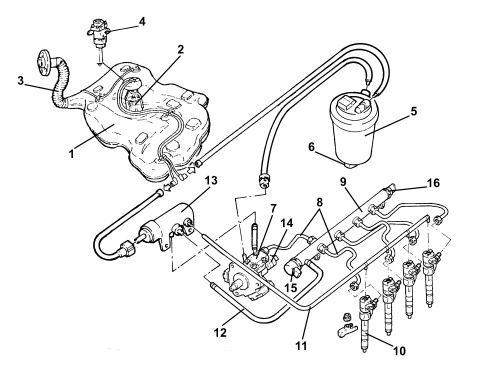
1 - Fuel tank
2 - Submerged fuel assembly complete with level gauge control
3 - Fuel filler pipe
4 - Inertia switch
5 - Fuel filter filter element
6 - Water in fuel filter sensor
7 - Pressure pump
8 - High pressure pipes
9 - Single fuel manifold pipe (rail)
10 - Injectors
11 - Pipe from injectors to fuel return manifold pipe
12 - Return pipe from rail to fuel return manifold pipe
13 - Fuel return manifold pipe
14 - Fuel pressure regulator on pump
15 - Fuel pressure regulator on rail
SPECIFICATIONS
The fuel system is divided into a low pressure circuit and a high pressure circuit.
The low pressure circuit consists of:
- submerged auxiliary pump complete with fuel level gauge, pressure regulator and fuel filter.
The high pressure circuit consists of:
- pressure pump;
- high pressure pipe (to be replaced at every dismantling);
- distribution manifold (rail) with pressure regulator and fuel pressure sensor;
- injectors.
The pressure regulator integrated in the fuel pump assembly is set at 3.5 bar.
With the key inserted the pressure throughout the low pressure line and the high pressure line is 3.5 bar and the pressure regulator is closed in these conditions.
The pressure in the distribution manifold (rail) is about 4.5 bar during starting because the high pressure pump is not capable of instantly providing high pressure.
The pressure in the rail can reach a maximum of 100 bar during operation depending on the engine load conditions and the performance requested by the driver.
When the engine is switched off, the pressure in the rail gradually decreases (via the high pressure pump) until it reaches around 4.5 (pressure regulator setting).
The maximum pressure produced by the high pressure pump is around 120 bar (if the pressure regulator is stuck).
The system is equipped with an inertia switch that cuts off the fuel supply from the fuel pump if the vehicle crashes.
The fuel pipes are fastened to the underbody by means of special support bands with special protection.
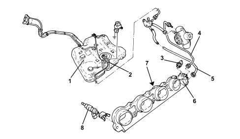
1. Fuel tank
2. Submerged fuel pump
3. Fuel pressure sensor
4. High pressure pipe
5. Low pressure pipe
6. Pressure regulator
7. Fuel distribution manifold
8. Injectors
Fuel supply system
SUBMERGED PUMP ASSEMBLY COMPLETE WITH LEVEL GAUGE
This consists essentially of:
- an electric fuel pump (1)
- a fuel filter (2)
- a float level level gauge (3)
- a diaphragm pressure regulator (4) (calibrated at 4.5 bar)
- a mesh prefilter (5).
An O-ring ensures the seal between the pump cover and the tank.
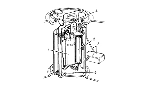
Fuel pump
The fuel pump is equipped with a permanent magnet electric motor (1) that controls the pump (2) and a terminal mount cover (3) that contains the electrical and hydraulic connections.
The pump stage is single, peripheral flow type with high performance under low voltage and temperature conditions.
The advantages compared to pumps that operate on volumetric princples are as follows:
- reduced weight
- limited size.
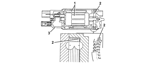
INERTIA SWITCH
The inertia switch, fitted under the driver''s seat on the right side, cuts off the fuel pump earth connection if the vehicle crashes and thus cuts off the fuel flow to the injection system.
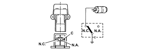
A steel ball (1) fitted in a tapered housing (2) is normally held in place by the attractive force of an adjacent magnet.
Under specific acceleration loads, the ball is released from the magnetic detent and gradually emerges from the tapered mount. Its upward movement is dependent on cone angle.
A rapid release mechanism (3) over the ball forms a normally closed (NC) electrical circuit.
When struck by the ball, the mechanism changes position from a NC circuit to a normally open (NA) circuit and breaks the fuel pump earth circuit.
The switch may be reset by pressing a button protected by a flexible cover (4).

If a smell of fuel or fuel system leaks are noted after even an apparently slight impact, do not reset the inertia switch but find and repair the fault to prevent the risk of fire. Otherwise, if no leaks are noted and the vehicle can be driven away, press the button to reactivate the pump.
FUEL SUPPLY SYSTEM
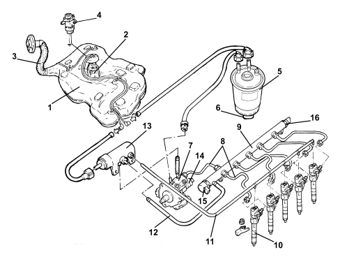
1 - Fuel tank
2 - Submerged fuel assembly complete with level gauge control
3 - Fuel filler pipe
4 - Inertia switch
5 - Fuel filter filter element
6 - Water in fuel filter sensor
7 - Pressure pump
8 - High pressure pipes
9 - Single fuel manifold pipe (rail)
10 - Injectors
11 - Pipe from injectors to fuel return manifold pipe
12 - Return pipe from rail to fuel return manifold pipe
13 - Fuel return manifold pipe
14 - Fuel pressure regulator on pump
15 - Fuel pressure regulator on rail
16 - Fuel pressure sensor
CONSTRUCTION SPECIFICATIONS
This fuel injection system used a high injection pressure under electronic control and a fuel delivery method known as a pilot injection that is electronically controlled by the electronic injection system via the injector (instead of being controlled by the injection pump as in previous direct injection engines).
Pressure level is the basic parameter for optimising fuel consumption and exhaust fume levels.
A pilot injection makes it possible to preheat the combustion chamber to avoid the pressure peak causd by rapid combustiojn and ensure smoother running.
Injection pressure regulation is made possible by the constructional features of the system, which is equipped with separate pressure pump and injectors, both managed by a control unit. In this way, injection pressure is independent of engine rotation speed.
The main features of the fuel feed system are as follows:
- high injection pressure (up to 1350 bar);
- injection pressure that can be modulated from 150 to 1350 bar under all engine operating conditions
- introduction of fuel up to 100 mm³/cycle within a speed range of 100 to 6000 rpm;
- precise injection control in terms of advance and duration;
- A pilot injection before TDC managed on the basis of rpm and engine load that allows pressure drift in the combustion chamber to be reduced to lower noise levels.
COMPOSITION
The fuel system is divided into a low pressure circuit and a high pressure circuit.
The low pressure circuit consists of:
- an auxiliary pump immersed in the tank;
- the fuel filter;
- the fuel return manifold pipe;
- the connecting pipes.
The high pressure circuit consists of:
- the pressure pump;
- the single fuel manifold pipe;
- the injectors;
- the connecting pipes.
Fuel system diagram
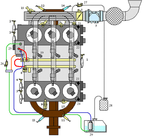
1. Rpm and TDC sensor
2. Left cylinder head exhaust camshaft timing sensor
3. Left cylinder head inlet camshaft timing sensor
4. Right cylinder head inlet camshaft timing sensor
5. Right cylinder head exhaust camshaft timing sensor
6. Throttle body
7. Flow meter (with intake air temperature sensor)
8. Fuel pressure sensor
9. Oil level and temperature sensor
10. Water temperature sensor
11. Right bank upstream Lambda sensor (pre-catalyzer)
12. Left bank upstream Lambda sensor (pre-catalyzer)
13. Right bank downstream Lambda sensor (post-catalyzer)
14. Left bank downstream Lambda sensor (post-catalyzer)
15. Absolute pressure sensor
16. Left bank detonation sensor
17. Right bank detonation sensor
18. Oil pressure sensor
19. Injectors
20. Coils
21. Left cylinder head exhaust camshaft phase transformer solenoid
22. Left cylinder head inlet camshaft phase transformer solenoid
23. Right cylinder head inlet camshaft phase transformer solenoid
24. Right cylinder head exhaust camshaft phase transformer solenoid
25. Flow regulator
26. Shut-off solenoid
27. Canister solenoid valve
28. Canister
29. Low pressure pump in tank
The fuel is taken from the tank by the low pressure electric pump and sent to the high pressure pump at a pressure of 6 bar regulated by a valve inside the pump; having reached the high pressure pump the pressure of the fuel increases to a maximum of 120 bar and it is sent to the left bank rail (red pipe in the drawing) from where, thanks to a connecting pipe between the two rails, it also reaches the right bank rail and with the injectors connected to the two rails and controlled by the engine management system the fuel is injected directly into the cylinders.
Before reaching the high pressure pump, the low pressure pipe that supplies the high pressure pump (shown in the drawing in blue), is connected by means of an eyelet drilled internally to the left rail to the duct that connects the rail to the low pressure pipe normally closed by the maximum pressure mechanical valve, calibated at 120 bar, located on the actual rail; when the pressure reaches the maximum permitted value, the maximum pressure valve opens and places the (high pressure) rail in contact with the (low pressure) supply pump thereby limiting the maximum pressure.
At the pump intake the fuel flows through a chamber that contains a damper which has the task of preventing the flow at the pump inlet from pulsating in order to guarantee the optimum supply for the high pressure pump; when it is working the damper produces fuel vapours that must be collected and there is a vapour recovery pipe for this purpose (shown in orange in the drawing) that has a return pipe connected to the high pressure pump damper chamber.
There is a fuel return pipe (shown in green in the drawing) from the high pressure pump taking the excess fuel to the tank; there is a shut-off solenoid valve on this pipe that is kept open by the control unit when the engine is running, whilst when the engine is switched off of the ignition is off the solenoid remains closed; all of this facilitates starting the engine preventing the high pressure pump from draining.
Low pressure fuel supply system
Hpi 4.6 electric pump assembly with level gauge and additional draught.
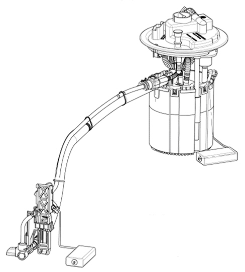
The special shape of the tank with two compartments necessary to allow the propeller shaft connected to the rear differential to reach the centre of the tank means that a special fuel draught system is required to convey the fuel from the compartment in the tank where the fuel pump is not housed in addition to a special fuel level gauge system.
A traditional type electric pump submerged in the tank is used with the fuel level sensor and float connected an an additional intake assembly located in the compartment of the tank where the pump is not submerged; the two compartments are in practice located on either side of the propeller shaft; the additional assembly has a second fuel level gauge sensor and float; the main pump and the additional assembly are connected by two pipes (one with a smaller section and one with a larger section) and by electrical wiring submerged in the tank with the connector on the electric pump also submerged.
Fuel draught
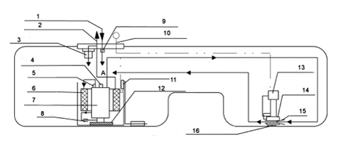
1. Return line
2. Supply line
3. Pressure regulator
4. Pressure relief valve
5. single-acting valve
6. Filter
8. Jet pump
9. Single-acting valve
10. Electrical output signal
11. Fuel level sensor attachment
12. Pump filter (60 micron)
13. Additional fuel level sensor attachment
14. Support in tank
15. Jet pump with filter
16. Additional filter (2000 micron)
To allow the intake of fuel from the additional compartment, a quantity of fuel is taken from the pump supply (A) which passes through the small section connecting pipe between the pump and the additional assembly and supplies the additional assembly jet pump (15) where, thanks to a Venturi pipe, the vacuum needed to allow the flow of fuel from the additional compartment to the main compartment housing the electric pump is created; in this way the gradual draining takes place firstly of the top part of the (shared) tank and later on of the additional compartment; obviously the compartment housing the electric pump will be drained last with the consumption of all the available fuel.
Fuel level reading
As already mentioned, two fuel level sensors with floats connected, one to the electric pump in the main compartment and one to the additional assembly (in the additional compartment) are used to give a correct fuel level reading; the two level sensors are connected in series and there is therefore a single connection that supplies the output fuel level reading; both sensors have a resistance that varies according to the position of the float and the series of the two constitutes the reading taken as a reference for the fuel level reading.
The float in the additional assembly is capable of travelling the entire height of the tank (from empty to full) whilst the float on the electric pump travles to about halfway up the tank.
Flow rate specifications
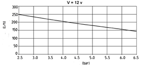
The above graph shows the pump outlet flow rate (l/h) dependent on the output pressure (bar) at a constant supply voltage of 12 V.
The flow rate for the pump working point is 125 l/h at a pressure of about 6.2 bar and a voltage of 12 volt.
Electrical connections
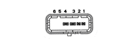
| DESCRIPTION | Pin component connector |
|---|---|
| Fuel level sensors supply | 1 |
| Fuel level sensors earth | 2 |
| Electric fuel pump earth | 3 |
| Electric fuel pump supply | 4 |
| Free | 5 |
| Free | 6 |
SPECIFICATIONS
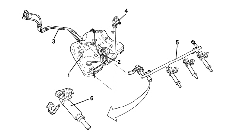
1. Fuel tank
2. Submerged fuel pump
3. Fuel pressure sensor
4. High pressure pipe
5. Low pressure pipe
6. Pressure regulator
Fuel supply system
SUBMERGED PUMP ASSEMBLY COMPLETE WITH LEVEL GAUGE
This consists essentially of:
- an electric fuel pump (1)
- a fuel filter (2)
- a float level level gauge (3)
- a diaphragm pressure regulator (4) (calibrated at 4.5 bar)
- a mesh prefilter (5).
An O-ring ensures the seal between the pump cover and the tank.
Fuel pump
The fuel pump is equipped with a permanent magnet electric motor (1) that controls the pump (2) and a terminal mount cover (3) that contains the electrical and hydraulic connections.
The pump stage is single, peripheral flow type with high performance under low voltage and temperature conditions.
The advantages compared to pumps that operate on volumetric princples are as follows:
- reduced weight
- limited size.
INERTIA SWITCH
The inertia switch, fitted under the driver''s seat on the right side, cuts off the fuel pump earth connection if the vehicle crashes and thus cuts off the fuel flow to the injection system.
A steel ball (1) fitted in a tapered housing (2) is normally held in place by the attractive force of an adjacent magnet.
Under specific acceleration loads, the ball is released from the magnetic detent and gradually emerges from the tapered mount. Its upward movement is dependent on cone angle.
A rapid release mechanism (3) over the ball forms a normally closed (NC) electrical circuit.
When struck by the ball, the mechanism changes position from a NC circuit to a normally open (NA) circuit and breaks the fuel pump earth circuit.
The switch may be reset by pressing a button protected by a flexible cover (4).
If a smell of fuel or fuel system leaks are noted after even an apparently slight impact, do not reset the inertia switch but find and repair the fault to prevent the risk of fire. Otherwise, if no leaks are noted and the vehicle can be driven away, press the button to reactivate the pump.
Parts & tools for this job Staging For 2005 Alfa Romeo 159
- PARTEngine gasket setSearch: Alfa Romeo 159 2005 engine gasket set
- TOOLTorque wrenchSearch: 3/8 inch torque wrench
- TOOLFeeler gauge setSearch: feeler gauge set
Links open Amazon search results in a new tab. As an Amazon Associate I earn from qualifying purchases.